Wiring Harness Connector; Fuel Hoses and Pillar- Page 197
Kubota L3560 Owners Manual
Table of Contents
ENGINE
L3560, L4060, L4760, L5060, L5460, L6060, WSM
1-S50
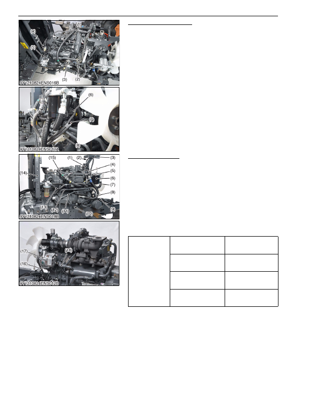
Wiring Harness Connector
1. Disconnect the injector connectors (1).
2. Disconnect the glow plug connector (4).
3. Disconnect the boost sensor connector (2), EGR valve
connector (3) and intake throttle sensor connector.
4. Disconnect the rail sensor connector (6), suction control valve
connector (7) and camshaft position sensor connector (8).
5. Set aside the main harness to the rear.
9Y1210824ENS0122US0
Fuel Hoses and Pillar
1. Disconnect the overflow hose (2), fuel hoses (4), then remove
the support (3) together with fuel sub tank (1).
2. Disconnect the overflow hose (5) and fuel hose (7), (8), (9), (13).
3. Disconnect the power steering delivery pipe (11).
4. Remove the power steering return pipe (12).
5. Remove the dipstick stay (10).
6. Remove the heater hose (15).
7. Remove the pillar (14).
8. Remove the fan belt (16) and alternator (17).
9. Remove the EGR cooler hose (18) and cooler pipe.
(When reassembling)
• Be sure to adjust the fan belt tension. (See page 1-S14.)
9Y1210824ENS0026US0
(1) Injector Connector
(2) Boost Sensor Connector
(3) EGR Valve Connector
(4) Glow Plug Connector
(5) Crankshaft Position Sensor
Connector
(6) Rail Sensor Connector
(7) Suction Control Valve Connector
(8) Camshaft Position Sensor
Tightening torque
Joint bolt for power steering
delivery pipe
40 to 49 N·m
4.0 to 5.0 kgf·m
29 to 36 lbf·ft
Retaining nut of power
steering delivery pipe
49 to 58 N·m
5.0 to 6.0 kgf·m
37 to 43 lbf·ft
Alternator mounting screw
(M10)
40 to 44 N·m
4.0 to 4.5 kgf·m
29 to 32 lbf·ft
Tension adjusting Screw
(M8)
18 to 20 N·m
1.8 to 2.1 kgf·m
13 to 15 lbf·ft
(1) Fuel Sub Tank
(2) Overflow Hose
(3) Support
(4) Fuel Hose
(5) Overflow Hose
(6) Fuel Filter
(7) Fuel Hose
(8) Fuel Hose
(9) Fuel Hose
(10) Dipstick Stay
(11) Power Steering Delivery Pipe
(12) Power Steering Return Pipe
(13) Fuel Hose
(14) Pillar
(15) Heater Hose
(16) Fan Belt
(17) Alternator
(18) EGR Cooler Hose
KiSC issued 03, 2016 A
Detailed Information for Kubota L3560 Owners Manual
Lists of information found in Kubota L3560 Owners Manual - Page 197
- 1. Disconnect the injector connectors (1).
- 2. Disconnect the glow plug connector (4).
- 3. Disconnect the boost sensor connector (2), EGR valve connector (3) and intake throttle sensor connector.
- 4. Disconnect the rail sensor connector (6), suction control valve connector (7) and camshaft position sensor connector (8).
- 5. Set aside the main harness to the rear.
- 1. Disconnect the overflow hose (2), fuel hoses (4), then remove the support (3) together with fuel sub tank (1).
- 2. Disconnect the overflow hose (5) and fuel hose (7), (8), (9), (13).
- 3. Disconnect the power steering delivery pipe (11).
- 4. Remove the power steering return pipe (12).
- 5. Remove the dipstick stay (10).
- 6. Remove the heater hose (15).
- 7. Remove the pillar (14).
- 8. Remove the fan belt (16) and alternator (17).
- 9. Remove the EGR cooler hose (18) and cooler pipe.
- 14.) 9Y1210824ENS0026US0 (1) Injector Connector (2) Boost Sensor Connector (3) EGR Valve Connector (4) Glow Plug Connector (5) Crankshaft Position Sensor Connector (6) Rail Sensor Connector (7) Suction Control Valve Connector (8) Camshaft Position Sensor Tightening torque Joint bolt for power steering delivery pipe 40 to 49 N·m 4.
- 5.0 kgf·m 29 to 36 lbf·ft Retaining nut of power steering delivery pipe 49 to 58 N·m 5.
- 6.0 kgf·m 37 to 43 lbf·ft Alternator mounting screw (M10) 40 to 44 N·m 4.
- 4.5 kgf·m 29 to 32 lbf·ft Tension adjusting Screw (M8) 18 to 20 N·m 1.
- Be sure to adjust the fan belt tension.