Mid Case Bearing Holder; Shaft Assemblies; PTO Clutch Valve- Page 385
Kubota L3560 Owners Manual
Table of Contents
TRANSMISSION
L3560, L4060, L4760, L5060, L5460, L6060, WSM
3-S66
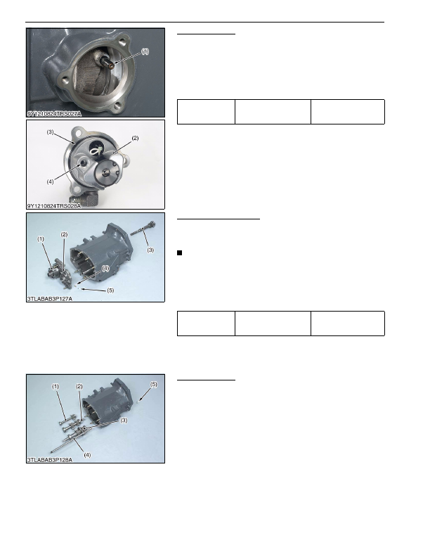
PTO Clutch Valve
1. Remove the PTO clutch valve (2) as a unit.
2. Pull out the pipe (1).
(When reassembling)
• Apply small amount of grease for the O-ring (3).
• Install the pipe (1) to the hole (4) of the PTO clutch valve (2)
firmly.
• Replace the pipe (1) with a new one.
9Y1210824TRS0023US0
Mid Case Bearing Holder
1. Remove the PTO drive shaft (3).
2. Remove the mid case bearing holder mounting screws.
3. Remove the bearing holder (2) with PTO clutch (1) as a unit.
NOTE
• Be careful not to fly out the ball (5) and spring (4) when pull
out the bearing holder (2).
(When reassembling)
• Tap in the mid case bearing holder (2) with plastic hummer until
contact to mid case, and then tighten the screws to specified
torque.
9Y1210824TRS0024US0
Shaft Assemblies
1. Remove the external snap ring (5).
2. Draw out the shaft assemblies (1), (2), (3) and shuttle fork rod
(4).
9Y1210824TRS0025US0
Tightening torque
PTO clutch valve mounting
screw
23.5 to 27.4 N·m
2.40 to 27.4 kgf·m
17.4 to 20.2 lbf·ft
(1) Pipe
(2) PTO Clutch Valve
(3) O-ring
(4) Hole
Tightening torque
Mid case bearing holder
mounting screw
48 to 55 N·m
4.9 to 5.7 kgf·m
36 to 41 lbf·ft
(1) PTO Clutch
(2) Mid Case Bearing Holder
(3) PTO Drive Shaft
(4) Spring
(5) Ball
(1) Reverse Gear Shaft
(2) Shuttle Gear Shaft
(3) Shuttle Shaft Assembly
(4) Shuttle Fork Rod
(5) External Snap Ring
KiSC issued 03, 2016 A
Detailed Information for Kubota L3560 Owners Manual
Lists of information found in Kubota L3560 Owners Manual - Page 385
- 1. Remove the PTO clutch valve (2) as a unit.
- 2. Pull out the pipe (1).
- 1. Remove the PTO drive shaft (3).
- 2. Remove the mid case bearing holder mounting screws.
- 3. Remove the bearing holder (2) with PTO clutch (1) as a unit.
- 1. Remove the external snap ring (5).
- 2. Draw out the shaft assemblies (1), (2), (3) and shuttle fork rod (4).
- 23.5 to 27.
- 2.40 to 27.
- 17.4 to 20.
- 4.9 to 5.
- Apply small amount of grease for the O-ring (3).
- Install the pipe (1) to the hole (4) of the PTO clutch valve (2) firmly.
- Replace the pipe (1) with a new one.
- Be careful not to fly out the ball (5) and spring (4) when pull out the bearing holder (2).
- Tap in the mid case bearing holder (2) with plastic hummer until contact to mid case, and then tighten the screws to specified torque.