Shaft Assemblies; Counter Shaft; Front Side- Page 401
Kubota L3560 Owners Manual
Table of Contents
TRANSMISSION
L3560, L4060, L4760, L5060, L5460, L6060, WSM
3-S82
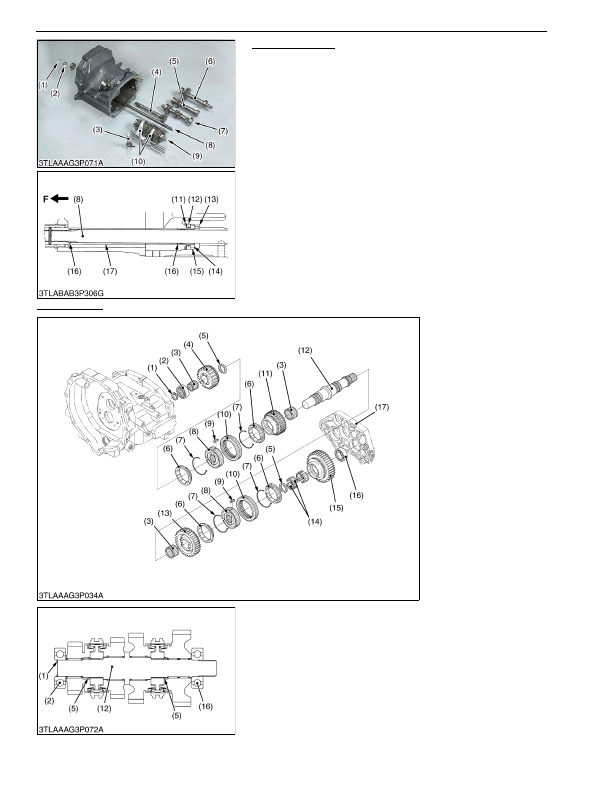
Shaft Assemblies
1. Remove the external snap ring (1) and thrust collar (2).
2. Draw out the shaft assemblies (4), (5), (6), (7), (9) and shift forks
(10) and rods.
3. Pull out the front axle drive shaft (8) to the rear side.
(When reassembling)
• Install the front axle drive shaft (8) from front side after
assembling the clutch housing and mid case. Then install the
bearing (13), sleeve (14), collar (15), oil seal (12), internal snap
ring (11), O-ring (16) and spacer (17) in order.
9Y1210824TRS0058US0
Counter Shaft
1. Remove the internal snap ring (1) and remove both side of the
bearings (2), (16).
2. Remove the gears on the counter shaft (12) and external snap
rings (5).
(When reassembling)
• Reinstall the synchronizer keys (9) in the key grooves of the
synchronizer rings (6) firmly.
9Y1210824TRS0059US0
(1) External Snap Ring
(2) Collar
(3) Shuttle Shift Arm
(4) 18T Gear Shaft Assembly
(5) Idle Shaft Assembly
(6) PTO Counter Shaft Assembly
(7) Main Gear Shaft Assembly
(8) Front Axle Drive Shaft
(9) Counter Shaft Assembly
(10) Shift Fork
(11) Internal Snap Ring
(12) Oil Seal
(13) Bearing
(14) Sleeve
(15) Collar
(16) O-ring
(17) Spacer
F:
Front Side
(1) Internal Snap Ring
(2) Bearing
(3) Needle Bearing
(4) 24T Gear (4th)
(5) External Snap Ring
(6) Synchronizer Ring
(7) Synchronizer Spring
(8) Hub
(9) Synchronizer Key
(10) Shifter
(11) 29T Gear (3rd)
(12) Counter Shaft
(13) 34T Gear (2nd)
(14) Needle Bearing
(15) 37T Gear (1st)
(16) Bearing
(17) Bearing Holder
KiSC issued 03, 2016 A
Detailed Information for Kubota L3560 Owners Manual
Lists of information found in Kubota L3560 Owners Manual - Page 401
- 1. Remove the external snap ring (1) and thrust collar (2).
- 2. Draw out the shaft assemblies (4), (5), (6), (7), (9) and shift forks (10) and rods.
- 3. Pull out the front axle drive shaft (8) to the rear side.
- 1. Remove the internal snap ring (1) and remove both side of the bearings (2), (16).
- 2. Remove the gears on the counter shaft (12) and external snap rings (5).
- Install the front axle drive shaft (8) from front side after assembling the clutch housing and mid case.
- Reinstall the synchronizer keys (9) in the key grooves of the synchronizer rings (6) firmly.