Brake Case; GST Valve Assembly- Page 410
Kubota L3560 Owners Manual
Table of Contents
TRANSMISSION
L3560, L4060, L4760, L5060, L5460, L6060, WSM
3-S91
Brake Case
1. Remove the range gear shift lever fulcrum screw.
2. Remove the brake case mounting screws and nuts.
3. Separate the brake case, tapping the brake case lever lightly.
(When reassembling)
• Apply grease to the steel ball seats. (Do not grease
excessively.)
• Apply liquid gasket (Three Bond 1208C or equivalent) to joint
face of the brake cae and transmission case.
• Apply liquid lock to the fulcrum screw.
• Be sure to apply liquid gasket to
"A"
position.
• Be sure to fix the brake cam and cam plate.
• Before installing the brake case to the transmission case, install
the cam plate to the transmission case.
9Y1210824TRS0036US0
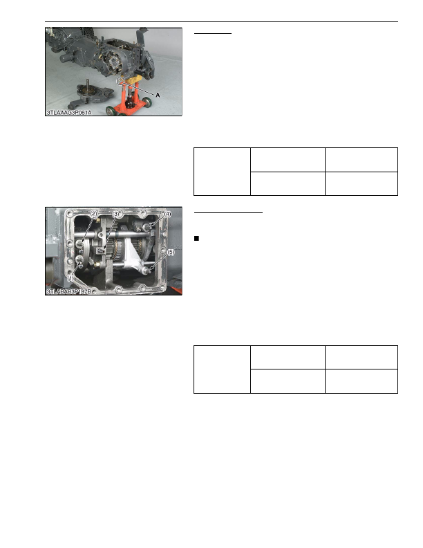
GST Valve Assembly
1. Remove the GST valve assembly with using two jack bolts.
2. Remove the shift pin (4).
NOTE
• Do not fall down the shift pin while disassembling.
(When reassembling)
• Place the 1-2 (1) and 3-4 (2) shift pins at
neutral
position,
sub-range shift pin (5) at
Hi
position (rearward) and main range
shift pin (4) at
"L"
position (forward), and then assemble the
GST valve.
• Be sure to match the each shift pin and shift piston.
• Install the GST valve by hand, and then tighten the screws. Do
not use the hummer.
• Apply liquid gasket (Three Bond 1208C or equivalent) to joint
face of the GST valve assembly.
• Replace the pipe (3) with a new one, if damaged.
9Y1210824TRS0073US0
Tightening torque
Brake case mounting screw
and nut
78 to 90 N·m
7.9 to 9.2 kgf·m
58 to 66 lbf·ft
Fulcrum screw
40 to 44 N·m
4.0 to 4.5 kgf·m
29 to 32 lbf·ft
Tightening torque
GST valve mounting screw
43 to 48 N·m
4.3 to 4.9 kgf·m
32 to 35 lbf·ft
Shift pin mounting screw
13 to 14 N·m
1.3 to 1.5 kgf·m
9.4 to 10 lbf·ft
(1) 1-2 Shift Pin
(2) 3-4 Shift Pin
(3) Pipe
(4) Main Range Shift Pin
(5) Sub-range Shift Pin
KiSC issued 03, 2016 A
Detailed Information for Kubota L3560 Owners Manual
Lists of information found in Kubota L3560 Owners Manual - Page 410
- 1. Remove the range gear shift lever fulcrum screw.
- 2. Remove the brake case mounting screws and nuts.
- 3. Separate the brake case, tapping the brake case lever lightly.
- 1. Remove the GST valve assembly with using two jack bolts.
- 2. Remove the shift pin (4).
- 7.9 to 9.
- 4.0 to 4.
- 4.3 to 4.
- 1.3 to 1.
- Apply grease to the steel ball seats.
- Apply liquid gasket (Three Bond 1208C or equivalent) to joint face of the brake cae and transmission case.
- Apply liquid lock to the fulcrum screw.
- Be sure to apply liquid gasket to "A" position.
- Be sure to fix the brake cam and cam plate.
- Before installing the brake case to the transmission case, install the cam plate to the transmission case.
- Do not fall down the shift pin while disassembling.
- Place the 1-2 (1) and 3-4 (2) shift pins at neutral position, sub-range shift pin (5) at Hi position (rearward) and main range shift pin (4) at "L" position (forward), and then assemble the GST valve.
- Be sure to match the each shift pin and shift piston.
- Install the GST valve by hand, and then tighten the screws.
- Apply liquid gasket (Three Bond 1208C or equivalent) to joint face of the GST valve assembly.
- Replace the pipe (3) with a new one, if damaged.