Brake Case- Page 483
Kubota L3560 Owners Manual
Table of Contents
BRAKES
L3560, L4060, L4760, L5060, L5460, L6060, WSM
5-S13
Brake Case
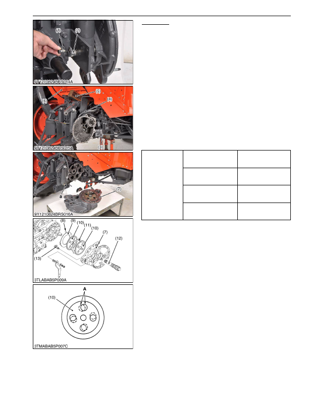
1. Remove the PTO cover.
2. Remove the screw (1) and displace the hydraulic cylinder pin (2)
to drawbar side.
3. Disconnect the brake rod (3).
4. Place a block of wood (5) between floor seat (6) and lift arm
support to support the floor seat. [ROPS type]
5. Remove the hydraulic cylinder hose (4).
6. Remove the brake case (7).
(When reassembling)
• Place the brake discs (10) so that the hole
"A"
of brake discs
should be overlapped 50 % or more.
• Apply liquid gasket (Three Bond 1208C or equivalent) to joint
face of the brake case and differential gear case.
• Apply the liquid lock to the fulcrum screw.
• Be sure to apply the liquid gasket to
"a"
position.
• Apply grease to the steel ball seats. (Do not grease
excessively.)
• Be sure to fix the brake cam (13) and cam plate (9).
• Before installing the brake case to the transmission case, install
the cam plate (9) to the transmission case.
9Y1210824BRS0010US0
Tightening torque
Brake case mounting screw
and nut
78 to 90 N·m
7.9 to 9.2 kgf·m
58 to 66 lbf·ft
Floor seat mounting bolt
and nut
200 to 220 N·m
20 to 23 kgf·m
150 to 160 lbf·ft
Fulcrum screw (Manual
tranmission and GST)
40 to 44 N·m
4.0 to 4.5 kgf·m
29 to 32 lbf·ft
Fulcrum screw (HST)
63 to 72 N·m
4.6 to 7.4 kgf·m
47 to 53 lbf·ft
(1) Screw
(2) Hydraulic Cylinder Pin
(3) Brake Rod
(4) Hydraulic Cylinder Hose
(5) Block of Wood
(6) Floor Seat
(7) Brake Case
(8) Steel Ball
(9) Cam Plate
(10) Brake Disc
(11) Plate
(12) Brake Shaft
(13) Brake Cam
KiSC issued 03, 2016 A
Detailed Information for Kubota L3560 Owners Manual
Lists of information found in Kubota L3560 Owners Manual - Page 483
- 1. Remove the PTO cover.
- 2. Remove the screw (1) and displace the hydraulic cylinder pin (2) to drawbar side.
- 3. Disconnect the brake rod (3).
- 4. Place a block of wood (5) between floor seat (6) and lift arm support to support the floor seat.
- 5. Remove the hydraulic cylinder hose (4).
- 6. Remove the brake case (7).
- 7.9 to 9.
- 4.0 to 4.
- 4.6 to 7.
- Place the brake discs (10) so that the hole "A" of brake discs should be overlapped 50 % or more.
- Apply liquid gasket (Three Bond 1208C or equivalent) to joint face of the brake case and differential gear case.
- Apply the liquid lock to the fulcrum screw.
- Be sure to apply the liquid gasket to "a" position.
- Apply grease to the steel ball seats.
- Be sure to fix the brake cam (13) and cam plate (9).
- Before installing the brake case to the transmission case, install the cam plate (9) to the transmission case.