Bevel Gear Case and Front Gear Case (L4760, L5060, L5460; Axle Flange and Front Gear Case; Bevel Gear and Bevel Gear Shaft- Page 500
Kubota L3560 Owners Manual
Table of Contents
FRONT AXLE
L3560, L4060, L4760, L5060, L5460, L6060, WSM
6-S10
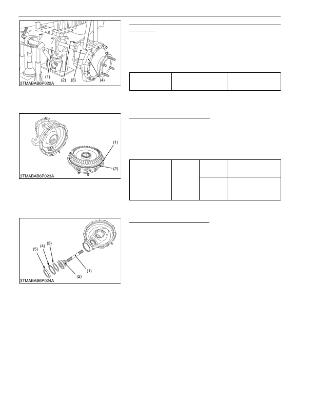
Bevel Gear Case and Front Gear Case (L4760, L5060, L5460
and L6060)
1. Remove the bevel gear case mounting screws.
2. Remove the bevel gear case (3) and front gear case (4) as a unit
from the front axle case (1).
(When reassembling)
• Apply grease to the O-ring (2) and be careful not to damage it.
• Do not interchange right and left bevel gear case assemblies.
9Y1210824FAS0015US0
Axle Flange and Front Gear Case
1. Remove the axle flange mounting screws.
2. Remove the axle flange (1).
(When reassembling)
• Apply grease to the O-ring (2) of axle flange.
• Tighten the axle flange mounting screws and nuts diagonally in
several steps.
9Y1210824FAS0016US0
Bevel Gear and Bevel Gear Shaft
1. Remove the plug (5).
2. Remove the internal snap ring (4) and shim (3).
3. Tap out the bevel gear (2) with ball bearing.
4. Draw out the bevel gear shaft (1).
9Y1210824FAS0017US0
Tightening torque
Bevel gear case mounting
screw
167 to 196 N·m
17.0 to 20.0 kgf·m
123 to 144 lbf·ft
(1) Front Axle Case
(2) O-ring
(3) Bevel Gear Case
(4) Front Gear Case
Tightening torque
Axle flange
mounting
screw and
nut
L3560
L4060
24 to 27 N·m
2.4 to 2.8 kgf·m
18 to 20 lbf·ft
L4760
L5060
L5460
L6060
30 to 34 N·m
3.0 to 3.5 kgf·m
22 to 25 lbf·ft
(1) Axle Flange
(2) O-ring
(1) Bevel Gear Shaft
(2) Bevel Gear
(3) Shim
(4) Internal Snap Ring
(5) Plug
KiSC issued 03, 2016 A
Detailed Information for Kubota L3560 Owners Manual
Lists of information found in Kubota L3560 Owners Manual - Page 500
- 1. Remove the bevel gear case mounting screws.
- 2. Remove the bevel gear case (3) and front gear case (4) as a unit from the front axle case (1).
- 1. Remove the axle flange mounting screws.
- 2. Remove the axle flange (1).
- 1. Remove the plug (5).
- 2. Remove the internal snap ring (4) and shim (3).
- 3. Tap out the bevel gear (2) with ball bearing.
- 4. Draw out the bevel gear shaft (1).
- 17.0 to 20.
- 2.4 to 2.
- 3.0 to 3.
- Apply grease to the O-ring (2) and be careful not to damage it.
- Do not interchange right and left bevel gear case assemblies.
- Apply grease to the O-ring (2) of axle flange.
- Tighten the axle flange mounting screws and nuts diagonally in several steps.