(2) Main Switch (CABIN Type); Connector Voltage; Main Switch at ON Position- Page 699
Kubota L3560 Owners Manual
Table of Contents
ELECTRICAL SYSTEM
L3560, L4060, L4760, L5060, L5460, L6060, WSM
9-S61
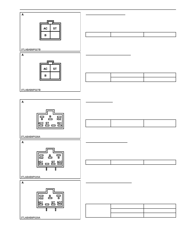
Main Switch at ON Position
1. Turn the main switch
"ON"
position.
2. Measure the resistance across the
B
terminal and the
AC
terminal.
3. If 0 ohm is not indicated, renew the main switch.
9Y1210824ELS0061US0
Main Switch at START Position
1. Turn and hold the main switch at the
"START"
position.
2. Measure the resistances across the
B
terminal and the
AC
terminal, and across the
B
terminal, and the
ST
terminal.
3. If 0 ohm is not indicated, renew the main switch.
9Y1210824ELS0062US0
(2) Main Switch (CABIN Type)
Connector Voltage
1. Measure the voltage across the connector
B
terminal and
chassis.
2. If the voltage differs from the battery voltage (11 to 14 V), the
wiring harness is faulty.
9Y1210824ELS0063US0
Main Switch at ACC Position
1. Turn the main switch
ACC
position.
2. Measure the resistance across the
B
terminal and the
ACC
terminal.
3. If 0 ohm is not indicated, renew the main switch.
9Y1210824ELS0064US0
Main Switch at Key ON Position
1. Turn and hold the main switch at the
"ON"
position.
2. Measure the resistances across the
B
terminal and the
ACC
terminal, across
B
terminal and
IG1
terminal and
B
terminal and
IG2
terminal.
3. If 0 ohm is not indicated, renew the main switch.
9Y1210824ELS0065US0
Resistance
B
terminal –
AC
terminal
0 Ω
A: Main Switch Side Connector 4C
Resistance
B
terminal –
AC
terminal
0 Ω
B
terminal –
ST
terminal
0 Ω
A: Main Switch Side Connector 4C
Voltage
Connector
B
terminal –
Chassis
Approx. battery voltage
A: Wire Harness Side Connector 6G
Resistance
B
terminal –
ACC
terminal
0 Ω
A: Main Switch Side Connector 6G
Resistance
B
terminal –
ACC
terminal
0 Ω
B
terminal –
IG1
terminal
0 Ω
B
terminal –
IG2
terminal
0 Ω
A: Main Switch Side Connector 6G
KiSC issued 03, 2016 A
Detailed Information for Kubota L3560 Owners Manual
Lists of information found in Kubota L3560 Owners Manual - Page 699
- 1. Turn the main switch "ON" position.
- 2. Measure the resistance across the B terminal and the AC terminal.
- 3. If 0 ohm is not indicated, renew the main switch.
- 1. Turn and hold the main switch at the "START" position.
- 2. Measure the resistances across the B terminal and the AC terminal, and across the B terminal, and the ST terminal.
- 3. If 0 ohm is not indicated, renew the main switch.
- 1. Measure the voltage across the connector B terminal and chassis.
- 2. If the voltage differs from the battery voltage (11 to 14 V), the wiring harness is faulty.
- 1. Turn the main switch ACC position.
- 2. Measure the resistance across the B terminal and the ACC terminal.
- 3. If 0 ohm is not indicated, renew the main switch.
- 1. Turn and hold the main switch at the "ON" position.
- 2. Measure the resistances across the B terminal and the ACC terminal, across B terminal and IG1 terminal and B terminal and IG2 terminal.
- 3. If 0 ohm is not indicated, renew the main switch.