(3) Safety Switch; 1) Connector Voltage; 1 (a)- Page 700
Kubota L3560 Owners Manual
Table of Contents
ELECTRICAL SYSTEM
L3560, L4060, L4760, L5060, L5460, L6060, WSM
9-S62
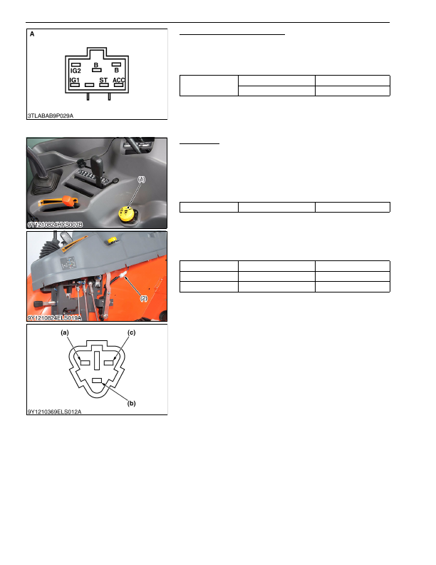
Main Switch at START Position
1. Turn and hold the main switch at the
"START"
position.
2. Measure the resistances across the
B
terminal and the
IG1
terminal, and across the
B
terminal, and the
ST
terminal.
3. If 0 ohm is not indicated, renew the main switch.
9Y1210824ELS0066US0
(3) Safety Switch
PTO Switch
1) Connector Voltage
1. Remove the PTO switch connector (2).
2. Turn the main switch
"ON"
position.
3. Measure the voltage across terminal
2 (Harness)
and chassis.
4. If the voltage differs from battery voltage, the wiring harness,
fuse, or main switch is faulty.
2) PTO Switch Continuity
1. Remove the PTO switch connector (1).
2. Check the continuity with an ohmmeter across the terminal
1 (a)
and terminal
2 (b)
, terminal
2 (b)
and terminal
3 (c)
.
3. If connection does not change, PTO switch is faulty.
9Y1210824ELS0067US0
Resistance
B
terminal –
IG1
terminal
0 Ω
B
terminal –
ST
terminal
0 Ω
A: Main Switch Side Connector 6G
Voltage
Terminal
2
– Chassis
Approx. battery voltage
Position
Terminal
1
– terminal
2
Terminal
2
– terminal
3
OFF
0 Ω
Infinity
ON
Infinity
0 Ω
(1) PTO Switch
(2) PTO Switch Connector
(a) Terminal 1
(b) Terminal 2
(c) Terminal 3
KiSC issued 03, 2016 A
Detailed Information for Kubota L3560 Owners Manual
Lists of information found in Kubota L3560 Owners Manual - Page 700
- 1. Turn and hold the main switch at the "START" position.
- 2. Measure the resistances across the B terminal and the IG1 terminal, and across the B terminal, and the ST terminal.
- 3. If 0 ohm is not indicated, renew the main switch.
- 1. Remove the PTO switch connector (2).
- 2. Turn the main switch "ON" position.
- 3. Measure the voltage across terminal 2 (Harness) and chassis.
- 4. If the voltage differs from battery voltage, the wiring harness, fuse, or main switch is faulty.
- 1. Remove the PTO switch connector (1).
- 2. Check the continuity with an ohmmeter across the terminal 1 (a) and terminal 2 (b) , terminal 2 (b) and terminal 3 (c) .
- 3. If connection does not change, PTO switch is faulty.