(5) Relays; 1) Checking Connector Voltage; Functional Check- Page 704
Kubota L3560 Owners Manual
Table of Contents
ELECTRICAL SYSTEM
L3560, L4060, L4760, L5060, L5460, L6060, WSM
9-S66
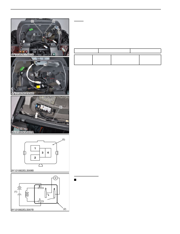
(5) Relays
Relays
1) Checking Connector Voltage
1. Remove the panel cover and panel.
2. Remove the relays.
3. Measure the voltage with a voltmeter across the battery terminal
and chassis as table below.
4. If the voltage differs from the battery voltage, the wiring harness
or fuse is faulty.
9Y1210824ELS0075US0
Functional Check
NOTE
• The relays described here are used same ones so that
these are interchangeable.
1. Apply the battery voltage across the terminal
1
and
2
, and check
for continuity across the terminal
3
and
4
.
2. If continuity is not established across the terminal
3
and
4
,
replace it.
9Y1210824ELS0076US0
Voltage
Terminal
4
– Chassis
Approx. battery voltage
Resistance
3
terminal –
4
terminal
Battery voltage is
applied across
1
terminal and
2
terminal
0 Ω
(1) Starter Relay
(2) Lamp Relay
(3) Compressor Relay (CABIN Type)
(4) Blower Relay (CABIN Type)
(5) Connector (Wire Harness side)
(1) Battery
(2) Connector (Relay)
KiSC issued 03, 2016 A
Detailed Information for Kubota L3560 Owners Manual
Lists of information found in Kubota L3560 Owners Manual - Page 704
- 1. Remove the panel cover and panel.
- 2. Remove the relays.
- 3. Measure the voltage with a voltmeter across the battery terminal and chassis as table below.
- 4. If the voltage differs from the battery voltage, the wiring harness or fuse is faulty.
- 1. Apply the battery voltage across the terminal 1 and 2 , and check for continuity across the terminal 3 and 4 .
- 2. If continuity is not established across the terminal 3 and 4 , replace it.
- The relays described here are used same ones so that these are interchangeable.