2. OPERATION; During Braking- Page 469
Kubota L3560 Owners Manual
Table of Contents
BRAKES
L3560, L4060, L4760, L5060, L5460, L6060, WSM
5-M2
2. OPERATION
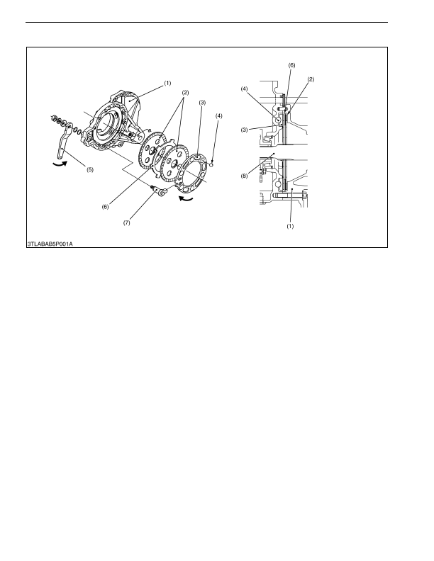
The brakes are provided on the power transmitting shafts (brake shafts (8)) through which power is transmitted
to the final reduction system. The brakes are incorporated in the brake case (1) filled with transmission oil. They are
designed to brake when the brake discs (2), spline-coupled and rotating with the brake shaft (8), are pressed against
the brake case (1) by cam plate (3) with the cam mechanism incorporating steel balls (4). For greater braking force,
two brake discs (2) are provided respectively, and the plate (6) fixed to the brake case (1) are arranged between the
brake discs (2).
During Braking
When the brake pedal is pressed, the force causes the brake cam lever (5) to move in the direction of allow
through the brake rod. At the same time, the brake cam (7) spline-couples with the brake cam lever (5) also moves.
Due to this force, cam plate (3) moves in the direction of arrow. Since the steel balls (4) are set in the grooves of
differential case, cam plate (3) is pushed out against the brake discs (2), causing braking with the friction force
created.
9Y1210824BRM0002US0
(1) Brake Case
(2) Brake Disc
(3) Cam Plate
(4) Steel Ball
(5) Brake Cam Lever
(6) Plate
(7) Brake Cam
(8) Brake Shaft
KiSC issued 03, 2016 A
Detailed Information for Kubota L3560 Owners Manual
Lists of information found in Kubota L3560 Owners Manual - Page 469
- 2. OPERATION The brakes are provided on the power transmitting shafts (brake shafts (8)) through which power is transmitted to the final reduction system.