7. SERVICING; [1] CYLINDER HEAD AND VALVES; Top Clearance- Page 223
Kubota L3560 Owners Manual
Table of Contents
ENGINE
L3560, L4060, L4760, L5060, L5460, L6060, WSM
1-S76
7. SERVICING
[1] CYLINDER HEAD AND VALVES
Top Clearance
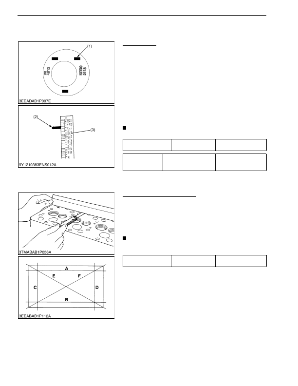
1. Remove the cylinder head.
2. With the piston at TDC, use grease to affix three or four
plastigauges (1) of a diameter 1.5 mm (0.059 in.) × 5.0 to
7.0 mm (0.20 to 0.27 in.) long to the crown of the piston; keep
the gauges away from the intake valve and combustion
chamber fittings.
3. Take the piston to an intermediate position, install the cylinder
head and tighten the head screws to the specified torque.
4. Turn the crankshaft so the piston goes through TDC.
5. Remove the cylinder head and compare the width of the
crushed plastigauges (2) with the scale (3).
6. If they are out of spec, check the oil clearance of the crank pin,
journals and piston pin.
NOTE
• Top clearance = Width of the crushed plastigauge (2).
9Y1210824ENS0068US0
Cylinder Head Surface Flatness
1. Clean the cylinder head surface.
2. Put a straightedge on the cylinder head.
3. Measure the clearance with a feeler gauge at the 6 places (see
the figure).
4. If the measurement is more than the allowable limit, make it
straight with a surface grinder.
IMPORTANT
• Do not put a straightedge on the combustion chamber.
• Examine the valve recessing after you correct.
9Y1210824ENS0069US0
Top clearance
Factory specification
0.60 to 0.70 mm
0.024 to 0.027 in.
Tightening torque
Cylinder head screws
93.2 to 98.0 N·m
9.50 to 10.0 kgf·m
68.8 to 72.3 lbf·ft
(1) Plastigauge
(2) Crushed Plastigauge
(3) Scale
Cylinder head surface
flatness
Allowable limit
0.05 mm
0.002 in.
KiSC issued 03, 2016 A
Detailed Information for Kubota L3560 Owners Manual
Lists of information found in Kubota L3560 Owners Manual - Page 223
- 7. SERVICING [1] CYLINDER HEAD AND VALVES Top Clearance 1.
- 2. With the piston at TDC, use grease to affix three or four plastigauges (1) of a diameter 1.
- 5.0 to 7.
- 3. Take the piston to an intermediate position, install the cylinder head and tighten the head screws to the specified torque.
- 4. Turn the crankshaft so the piston goes through TDC.
- 5. Remove the cylinder head and compare the width of the crushed plastigauges (2) with the scale (3).
- 6. If they are out of spec, check the oil clearance of the crank pin, journals and piston pin.
- 1. Clean the cylinder head surface.
- 2. Put a straightedge on the cylinder head.
- 3. Measure the clearance with a feeler gauge at the 6 places (see the figure).
- 4. If the measurement is more than the allowable limit, make it straight with a surface grinder.
- 93.2 to 98.
- 9.50 to 10.
- 68.8 to 72.
- Top clearance = Width of the crushed plastigauge (2).
- Do not put a straightedge on the combustion chamber.
- Examine the valve recessing after you correct.