[2] REAR HYDRAULIC BLOCK; [3] POSITION CONTROL VALVE; A: From Hydraulic Pump- Page 537
Kubota L3560 Owners Manual
Table of Contents
HYDRAULIC SYSTEM
L3560, L4060, L4760, L5060, L5460, L6060, WSM
8-M8
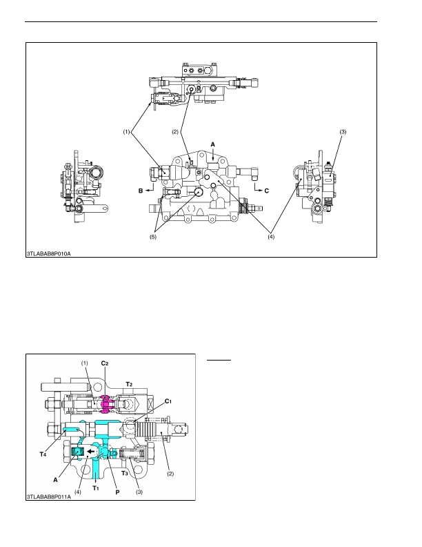
[2] REAR HYDRAULIC BLOCK
The rear hydraulic block is equipped with cylinder safety valve (1), lowering speed adjusting valve (2) and check
valve (5), etc. besides hydraulic outlet port.
The hydraulic outlet port is located top of the rear hydraulic block to take power out from the tractor to operate the
hydraulic cylinders on the implement.
9Y1210824HYM0008US0
[3] POSITION CONTROL VALVE
Neutral
Pressurized oil flows at the
P
port, pushes open
unload poppet 1 (4) and returns to tank from
T1
port.
The oil in the chamber
A
behind the unload poppet 1
(4) returns to the tank from
T4
port. The oil in the
hydraulic cylinder does not flow out because the circuit
is cut off by the actions of poppet 2 (1) and check valve
in the rear hydraulic block.
This allows the implement to be kept at a steady
height.
9Y1210824HYM0009US0
(1) Cylinder Safety Valve
(2) Lowering Speed Adjusting
Valve
(3) Position Control Valve
(4) Cover (Rear Hydraulic Outlet
Port)
(5) Check Valve
A: From Hydraulic Pump
B: To or From Hydraulic
Cylinder
C: To or From Hydraulic
Cylinder
(1) Poppet 2
(2) Spool
(3) Unload Poppet 2
(4) Unload Poppet 1
A: Chamber A
P:
Pump Port
C1: Cylinder Port 1
C2: Cylinder Port 2
T1: Tank Port 1
T2: Tank Port 2
T3: Tank Port 3
T4: Tank Port 4
KiSC issued 03, 2016 A