[8] LIGHTING SYSTEM; (1) Multi Function Combination Lever (Combination Switch); Multi Function Combination Lever Switch- Page 707
Kubota L3560 Owners Manual
Table of Contents
ELECTRICAL SYSTEM
L3560, L4060, L4760, L5060, L5460, L6060, WSM
9-S69
No-Load Test
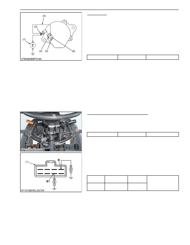
1. Connect the
2P
connector (6) to previous positions of the
alternator after turning the main switch
OFF
.
2. Connect the jumper lead (3) between
IG
terminal (4) and
B
terminal (2).
3. Start the engine and then set at idling speed.
4. Disconnect the negative cable from the battery.
5. Measure the voltage between the
B
terminal (2) and the
chassis.
6. If the measurement is less than the factory specifications,
disassemble the alternator and check the IC regulator.
(Reference)
• Once the engine started, the alternator temperature increases
quickly up to an ambient temperature of 70 to 90 °C (158 to
194 °F). As the temperature goes higher than 50 °C (122 °F),
the alternator voltage slowly decreases; at higher than 100 °C
(212 °F), it decreases by about 1 V.
9Y1210824ELS0083US0
[8] LIGHTING SYSTEM
(1) Multi Function Combination Lever (Combination Switch)
Multi Function Combination Lever Switch
1. Remove the steering post cover 1.
2. Disconnect the multi function combination lever switch
connector (2).
3. Perform the following checkings.
9Y1210824ELS0084US0
1) Connector Voltage
1. Measure the voltage across the connector
B
terminal to chassis
and the
B1
terminal to chassis when the main switch is
"OFF"
position.
2. If the voltage differs from the battery voltage, the wiring harness
is faulty.
9Y1210824ELS0085US0
Voltage
Factory specification
More than 14 V
(1) Voltmeter
(2)
B
Terminal
(3) Jumper Lead
(4)
IG
Terminal
(5)
L
Terminal
(6)
2P
Connector
Voltage
Factory specification
More than 14 V
(1) Multi Function Combination Lever
(2) Multi Function Combination Lever
Connector
Voltage
Main switch at
"OFF"
position
B
terminal–
Chassis
Battery voltage
Voltage
Main switch at
"OFF"
position
B1
terminal–
Chassis
(1) Connector of Wire Harness Side
KiSC issued 03, 2016 A
Detailed Information for Kubota L3560 Owners Manual
Lists of information found in Kubota L3560 Owners Manual - Page 707
- 1. Connect the 2P connector (6) to previous positions of the alternator after turning the main switch OFF .
- 2. Connect the jumper lead (3) between IG terminal (4) and B terminal (2).
- 3. Start the engine and then set at idling speed.
- 4. Disconnect the negative cable from the battery.
- 5. Measure the voltage between the B terminal (2) and the chassis.
- 6. If the measurement is less than the factory specifications, disassemble the alternator and check the IC regulator.
- 1. Remove the steering post cover 1.
- 2. Disconnect the multi function combination lever switch connector (2).
- 3. Perform the following checkings.
- 1. Measure the voltage across the connector B terminal to chassis and the B1 terminal to chassis when the main switch is "OFF" position.
- 2. If the voltage differs from the battery voltage, the wiring harness is faulty.
- Once the engine started, the alternator temperature increases quickly up to an ambient temperature of 70 to 90 °C (158 to 194 °F).