5. DISASSEMBLING AND ASSEMBLING; [1] HYDRAULIC PUMP; (1) Removing Hydraulic Pump Assembly- Page 567
Kubota L3560 Owners Manual
Table of Contents
HYDRAULIC SYSTEM
L3560, L4060, L4760, L5060, L5460, L6060, WSM
8-S14
5. DISASSEMBLING AND ASSEMBLING
[1] HYDRAULIC PUMP
IMPORTANT
• The hydraulic pump is precision machined and assembled: if disassemble once, it may be unable to keep
its original performance. Therefore, when the hydraulic pump fails, replacement should be done with the
hydraulic pump assembled except when emergency repair is unavoidable.
• When repair is required, follow the disassembly and servicing procedures shown below with utmost care.
• Be sure to test the hydraulic pump with a flowmeter before disassembling.
• After reassembly, be sure to perform break-in operation and ensure that there is nothing abnormal with
the hydraulic pump.
9Y1210824HYS0011US0
(1) Removing Hydraulic Pump Assembly
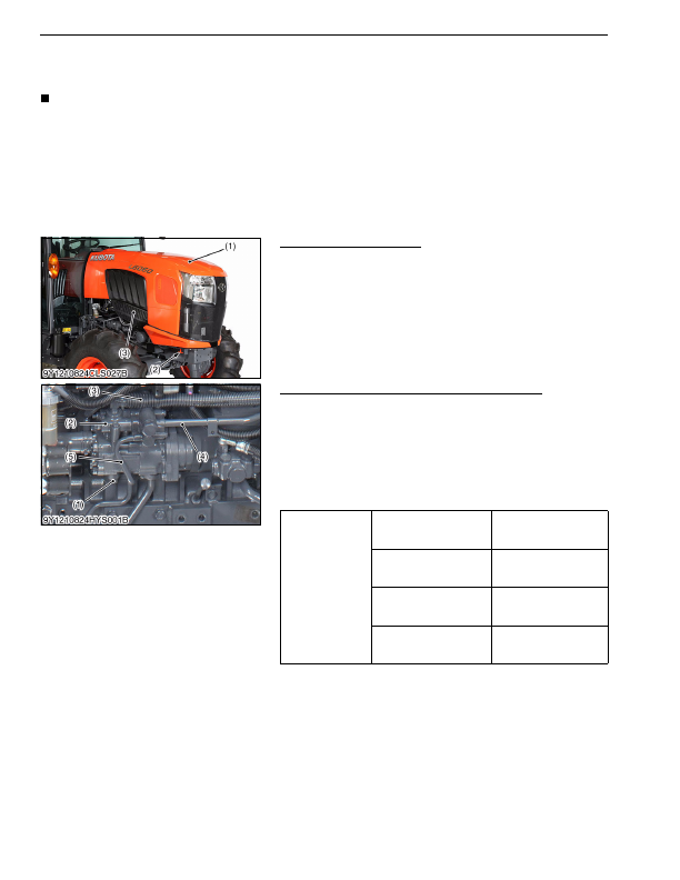
Bonnet and Side Skirt R.H.
1. Pull down the knob (2) and open the bonnet (1).
2. Remove the side skirt R.H. (3).
9Y1210824HYS0012US0
Regulating Valve (Manual Transmission and GST)
1. Disconnect the power steering delivery pipe (4) and return hose
(3).
2. Disconnect the PTO delivery pipe (5) and regulator delivery pipe
(1).
3. Remove the regulating valve (2).
(When reassembling)
• Apply grease to the O-ring and be careful not to damage it.
• Install the copper washers firmly.
9Y1210824HYS0013US0
(1) Bonnet
(2) Knob
(3) Side Skirt R.H.
Tightening torque
Power steering delivery
pipe joint bolt
40 to 49 N·m
4.0 to 5.0 kgf·m
29 to 36 lbf·ft
PTO delivery pipe joint bolt
35 to 39 N·m
3.5 to 4.0 kgf·m
26 to 28 lbf·ft
Regulator delivery pipe
joint bolt
40 to 49 N·m
4.0 to 5.0 kgf·m
29 to 36 lbf·ft
Regulating valve mounting
screw
18 to 20 N·m
1.8 to 2.1 kgf·m
13 to 15 lbf·ft
(1) Regulator Delivery Pipe
(2) Regulating Valve
(3) Return Hose
(4) Power Steering Delivery Pipe
(5) PTO Delivery Pipe
KiSC issued 03, 2016 A
Detailed Information for Kubota L3560 Owners Manual
Lists of information found in Kubota L3560 Owners Manual - Page 567
- 5. DISASSEMBLING AND ASSEMBLING [1] HYDRAULIC PUMP IMPORTANT • The hydraulic pump is precision machined and assembled: if disassemble once, it may be unable to keep its original performance.
- 1. Pull down the knob (2) and open the bonnet (1).
- 2. Remove the side skirt R.
- 1. Disconnect the power steering delivery pipe (4) and return hose (3).
- 2. Disconnect the PTO delivery pipe (5) and regulator delivery pipe (1).
- 3. Remove the regulating valve (2).
- 4.0 to 5.
- 3.5 to 4.
- 4.0 to 5.
- 1.8 to 2.
- The hydraulic pump is precision machined and assembled: if disassemble once, it may be unable to keep its original performance.
- When repair is required, follow the disassembly and servicing procedures shown below with utmost care.
- Be sure to test the hydraulic pump with a flowmeter before disassembling.
- After reassembly, be sure to perform break-in operation and ensure that there is nothing abnormal with the hydraulic pump.
- Apply grease to the O-ring and be careful not to damage it.
- Install the copper washers firmly.