[3] STEERING CYLINDER; Steering Cylinder; Front Wheel, Cylinder Cover and Tie-rod- Page 526
Kubota L3560 Owners Manual
Table of Contents
STEERING
L3560, L4060, L4760, L5060, L5460, L6060, WSM
7-S7
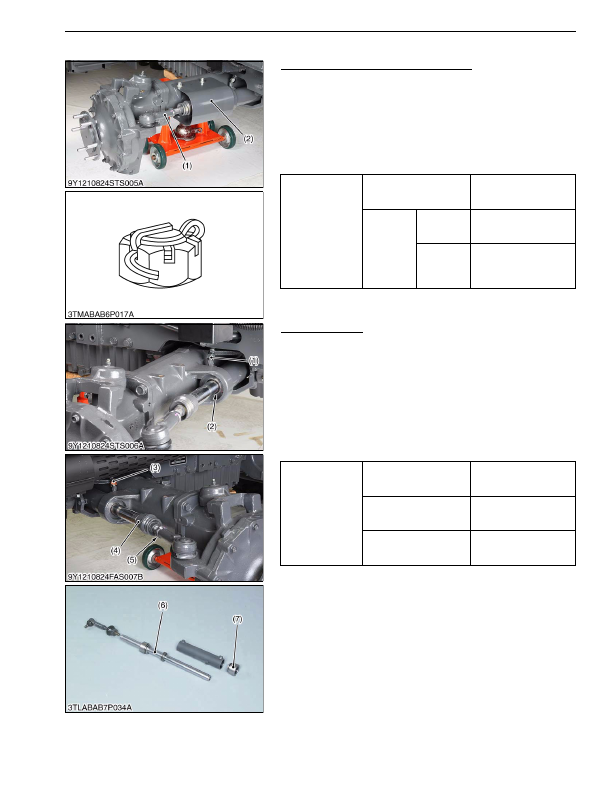
[3] STEERING CYLINDER
Front Wheel, Cylinder Cover and Tie-rod
1. Place a disassembly stand under the engine and support it with
a jack.
2. Remove the front wheel and cylinder cover (2).
3. Pull out the cotter pin and remove the tie-rod end slotted nut.
4. Disconnect the tie-rod (1).
(When reassembling)
• After tightening the tie-rod end slotted nut to the specified
torque, install a cotter pin as shown in the figure.
9Y1210824STS0008US0
Steering Cylinder
1. Disconnect the power steering hoses (1), (3) and remove the
elbows.
2. Disconnect the tie-rod joint L.H. (4).
3. Remove the internal snap ring (2).
4. Remove the steering cylinder to the left.
5. Remove the head cover (7) and draw out the cylinder rod (6).
(When reassembling)
• Apply transmission fluid to the oil seal and O-ring.
• Apply liquid lock (Three Bond 1324B or equivalent) to the thread
of tie-rod joint (4).
9Y1210824STS0009US0
Tightening torque
Front wheel mounting nut
137 N·m
14.0 kgf·m
101 lbf·ft
Tie-rod end
slotted nut
L3560
L4060
40 to 45 N·m
4.0 to 4.6 kgf·m
29 to 33 lbf·ft
L4760
L5060
L5460
L6060
157 to 176 N·m
16.0 to 18.0 kgf·m
116 to 130 lbf·ft
(1) Tie-rod
(2) Cylinder Cover
Tightening torque
Power steering hose
retaining nut
25 to 29 N·m
2.5 to 3.0 kgf·m
18 to 21 lbf·ft
Tie-rod joint
167 to 196 N·m
17.0 to 20.0 kgf·m
123 to 144 lbf·ft
Tie-rod joint lock nut
167 to 196 N·m
17.0 to 20.0 kgf·m
123 to 144 lbf·ft
(1) Power Steering Hose R.H.
(2) Internal Snap Ring
(3) Power Steering Hose L.H.
(4) Tie-rod Joint
(5) Lock Nut
(6) Cylinder Rod
(7) Head Cover
KiSC issued 03, 2016 A
Detailed Information for Kubota L3560 Owners Manual
Lists of information found in Kubota L3560 Owners Manual - Page 526
- 1. Place a disassembly stand under the engine and support it with a jack.
- 2. Remove the front wheel and cylinder cover (2).
- 3. Pull out the cotter pin and remove the tie-rod end slotted nut.
- 4. Disconnect the tie-rod (1).
- 1. Disconnect the power steering hoses (1), (3) and remove the elbows.
- 2. Disconnect the tie-rod joint L.
- 3. Remove the internal snap ring (2).
- 4. Remove the steering cylinder to the left.
- 5. Remove the head cover (7) and draw out the cylinder rod (6).
- 14.0 kgf·m 101 lbf·ft Tie-rod end slotted nut L3560 L4060 40 to 45 N·m 4.
- 4.6 kgf·m 29 to 33 lbf·ft L4760 L5060 L5460 L6060 157 to 176 N·m 16.
- 18.0 kgf·m 116 to 130 lbf·ft (1) Tie-rod (2) Cylinder Cover Tightening torque Power steering hose retaining nut 25 to 29 N·m 2.
- 3.0 kgf·m 18 to 21 lbf·ft Tie-rod joint 167 to 196 N·m 17.
- 17.0 to 20.
- After tightening the tie-rod end slotted nut to the specified torque, install a cotter pin as shown in the figure.
- Apply transmission fluid to the oil seal and O-ring.
- Apply liquid lock (Three Bond 1324B or equivalent) to the thread of tie-rod joint (4).