[4] HYDRAULIC CONTROL SYSTEM; (1) Hydraulic Circuit and System Outline; To Steering Controller- Page 287
Kubota L3560 Owners Manual
Table of Contents
TRANSMISSION
L3560, L4060, L4760, L5060, L5460, L6060, WSM
3-M11
[4] HYDRAULIC CONTROL SYSTEM
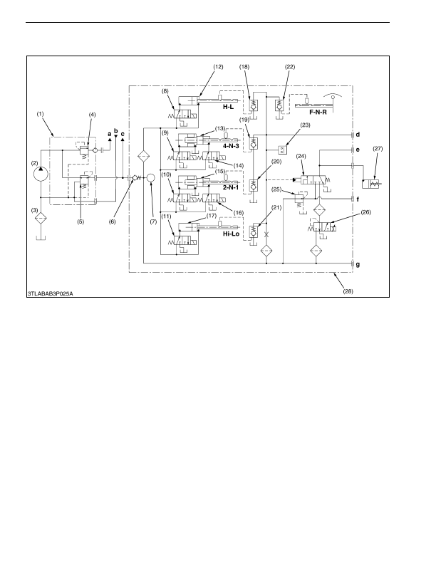
(1) Hydraulic Circuit and System Outline
1. Oil is supplied from the power steering hydraulic pump (2) while running the engine.
2. The oil entering the regulating valve assembly (1) flows through the pressure reducing valve (5) to the GST circuit.
This oil pressure is kept at a fixed level by the pressure reducing valve (5).
3. When the GST lever is operated, the desired shift solenoids (8), (9), (10), (11), (14) or (16) are excited according
to the output voltage from the GST lever sensor.
4. When the solenoid valve is operated, oil is supplied to corresponded shift pistons (12), (13), (15) or (17), and the
shift piston is moved. The shift arm that is moved by the shift piston moves shifter of synchromesh to shift the
gear. At this time, GST clutch (27) has been disengaging until gear shifting is completed.
The GST clutch (27) is engaging except where the condition is neutral, is gear shifting and is engine stopping.
5. Pressure in the pilot circuit rises because the shift check valves (18), (21) and (19) or (20) are shut by the
movements of shift pistons at the same time as completing gear shifting.
6. By means of pressure rising of the circuit, the clutch valve (24) is actuated. And, oil flows through the low-pass
valve (25) and the proportional reducing valve (26) to the GST clutch (27). This oil flows until becoming the
compound pressure which is both of setting pressure for closing of low-pass valve, and controlled indication
pressure of the proportional reducing valve.
(Reference)
• Setting pressure for closing of low-pass valve: 0.24 MPa (2.5 kgf/cm
2
, 34.1 psi)
(To be continued)
(1) Regulating Valve Assembly
(2) Hydraulic Pump
(3) Hydraulic Oil Filter
(4) Regulating Valve
(5) Pressure Reducing Valve
(6) Check Valve
(7) Oil Temperature Sensor
(8) Solenoid Valve 6
(Main Range Shift)
(9) Solenoid Valve 3
(10) Solenoid Valve 1
(11) Solenoid Valve 5
(Sub-range Shift)
(12) Shift Piston
(Main Range Shift)
(13) 3-4 Shift Piston
(14) Solenoid Valve 4
(15) 1-2 Shift Piston
(16) Solenoid Valve 2
(17) Shift Piston (Sub-range Shift)
(18) Shift Check Valve
(Main Range Shift)
(19) 3-4 Shift Check Valve
(20) 1-2 Shift Check Valve
(21) Shift Check Valve
(Sub-range Shift)
(22) Shift Check Valve, Shuttle
(23) Pressure Switch
(24) Clutch Valve
(25) Low-pass Valve
(26) Proportional Reducing Valve
(27) GST Clutch
(28) GST Valve Assembly
a:
To Steering Controller
b:
From Steering Controller
c:
To PTO Clutch Valve
d:
Check port for pilot
pressure
e:
Check port for clutch
pressure
f:
Check port for Low-pass
pressure
g:
Check port for system
pressure
KiSC issued 03, 2016 A
Detailed Information for Kubota L3560 Owners Manual
Lists of information found in Kubota L3560 Owners Manual - Page 287
- 1. Oil is supplied from the power steering hydraulic pump (2) while running the engine.
- 2. The oil entering the regulating valve assembly (1) flows through the pressure reducing valve (5) to the GST circuit.
- 3. When the GST lever is operated, the desired shift solenoids (8), (9), (10), (11), (14) or (16) are excited according to the output voltage from the GST lever sensor.
- 4. When the solenoid valve is operated, oil is supplied to corresponded shift pistons (12), (13), (15) or (17), and the shift piston is moved.
- 5. Pressure in the pilot circuit rises because the shift check valves (18), (21) and (19) or (20) are shut by the movements of shift pistons at the same time as completing gear shifting.
- 6. By means of pressure rising of the circuit, the clutch valve (24) is actuated.
- 2.5 kgf/cm 2 , 34.
- Setting pressure for closing of low-pass valve: 0.