5. DISASSEMBLING AND ASSEMBLING; [1] STARTER; [2] ALTERNATOR- Page 729
Kubota L3560 Owners Manual
Table of Contents
ELECTRICAL SYSTEM
L3560, L4060, L4760, L5060, L5460, L6060, WSM
9-S91
5. DISASSEMBLING AND ASSEMBLING
[1] STARTER
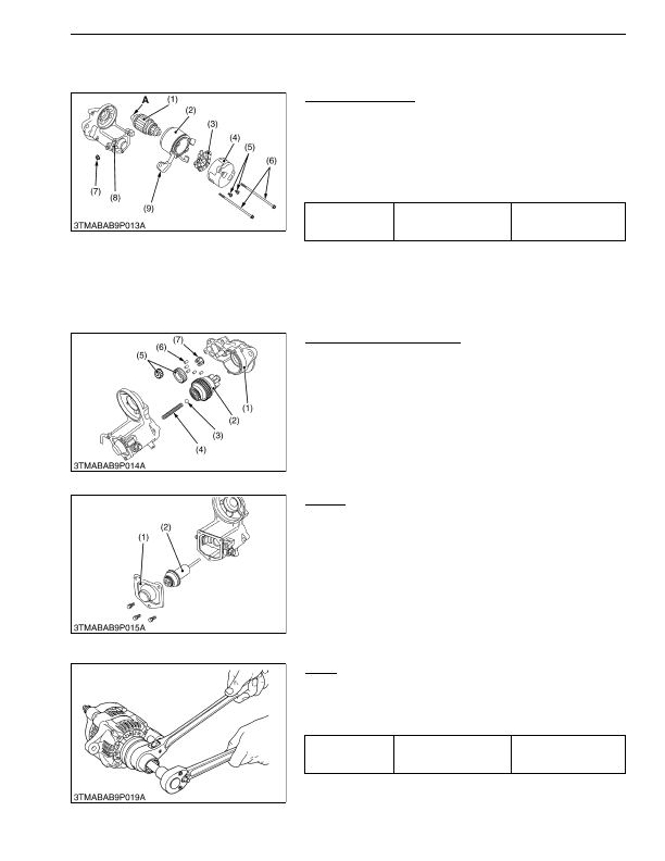
Disassembling Motor
1. Disconnect the connecting lead (9) from the magnet switch (8).
2. Remove the screws (6), and then separate the end frame (4),
yoke (2) and armature (1).
3. Remove the two screws (5).
4. Remove the brush holder (3) from the end frame (4).
(When reassembling)
• Apply grease to the spline teeth
"A"
of the armature (1).
9Y1210824ELS0133US0
Disassembling Magnet Switch
1. Remove the drive end frame (1) mounting screws.
2. Remove the overrunning clutch (2), ball (3), spring (4), gears
(5), rollers (6) and retainer (7).
(When reassembling)
• Apply grease to the gear teeth of the gears (5) and overrunning
clutch (2), and ball (3).
9Y1210824ELS0134US0
Plunger
1. Remove the end cover (1).
2. Remove the plunger (2).
9Y1210824ELS0135US0
[2] ALTERNATOR
Pulley
1. Secure the hexagonal end of the pulley shaft with a
double-ended ratchet wrench as shown in the figure.
2. Loosen the pulley nut with a socket wrench and remove it.
(When reassembling)
9Y1210824ELS0136US0
Tightening torque
Nut (7)
5.9 to 11 N·m
0.60 to 1.2 kgf·m
4.4 to 8.6 lbf·ft
(1) Armature
(2) Yoke
(3) Brush Holder
(4) End Frame
(5) Screw
(6) Screw
(7) Nut
(8) Magnet Switch
(9) Connecting Lead
A: Spline Teeth
(1) Drive End Frame
(2) Overrunning Clutch
(3) Ball
(4) Spring
(5) Gear
(6) Roller
(7) Retainer
(1) End Cover
(2) Plunger
Tightening torque
Pulley nut
58.4 to 78.9 N·m
5.95 to 8.05 kgf·m
43.1 to 58.2 lbf·ft
KiSC issued 03, 2016 A
Detailed Information for Kubota L3560 Owners Manual
Lists of information found in Kubota L3560 Owners Manual - Page 729
- 5. DISASSEMBLING AND ASSEMBLING [1] STARTER Disassembling Motor 1.
- 2. Remove the screws (6), and then separate the end frame (4), yoke (2) and armature (1).
- 3. Remove the two screws (5).
- 4. Remove the brush holder (3) from the end frame (4).
- 1. Remove the drive end frame (1) mounting screws.
- 2. Remove the overrunning clutch (2), ball (3), spring (4), gears (5), rollers (6) and retainer (7).
- 1. Remove the end cover (1).
- 2. Remove the plunger (2).
- 1. Secure the hexagonal end of the pulley shaft with a double-ended ratchet wrench as shown in the figure.
- 2. Loosen the pulley nut with a socket wrench and remove it.
- 5.9 to 11 N·m 0.
- 1.2 kgf·m 4.
- 8.6 lbf·ft (1) Armature (2) Yoke (3) Brush Holder (4) End Frame (5) Screw (6) Screw (7) Nut (8) Magnet Switch (9) Connecting Lead A: Spline Teeth (1) Drive End Frame (2) Overrunning Clutch (3) Ball (4) Spring (5) Gear (6) Roller (7) Retainer (1) End Cover (2) Plunger Tightening torque Pulley nut 58.
- 78.9 N·m 5.
- 8.05 kgf·m 43.
- Apply grease to the spline teeth "A" of the armature (1).
- Apply grease to the gear teeth of the gears (5) and overrunning clutch (2), and ball (3).