[4] CRANKSHAFT; Clearance between Piston Ring and Groove; Side Clearance of Crankshaft- Page 234
Kubota L3560 Owners Manual
Table of Contents
ENGINE
L3560, L4060, L4760, L5060, L5460, L6060, WSM
1-S87
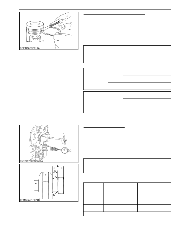
Clearance between Piston Ring and Groove
1. Clean the rings and the ring grooves, and install each ring in its
groove.
2. Measure the clearance between the ring and the groove with a
feeler gauge or depth gauge.
3. If the clearance is more than the allowable limit, replace the
piston ring.
4. If the clearance stays more than the allowable limit with new
ring, replace the piston also.
* D1803-CR-TE4 and V2403-CR-TE4 are key stone type.
9Y1210824ENS0095US0
[4] CRANKSHAFT
Side Clearance of Crankshaft
1. Set a dial indicator with its point on the end of the crankshaft.
2. Move the crankshaft to the front and rear to measure the side
clearance.
3. If the measurement is more than the allowable limit, replace the
thrust bearings.
4. If the same dimension bearing is not applicable because of the
crankshaft journal wear, replace it with an oversize one. Refer
to the table and figure.
(Reference)
• Oversize dimensions of crankshaft journal
9Y1210824ENS0096US0
Top ring
Factory
specifica-
tion
D1803-CR-E4,
V2403-CR-E4
0.050 to 0.090 mm
0.0020 to 0.0035 in.
Allowable
limit
D1803-CR-E4,
V2403-CR-E4
0.20 mm
0.0079 in.
Second ring
Factory
specifica-
tion
V2403-CR-TE4
0.0930 to 0.128 mm
0.00367 to 0.00503 in.
D1803-CR-E4
V2403-CR-E4
0.0780 to 0.110 mm
0.00307 to 0.00433 in.
Allowable limit
0.20 mm
0.0079 in.
Oil ring
Factory
specifica-
tion
V2403-CR-TE4
0.020 to 0.060 mm
0.00079 to 0.0023 in.
D1803-CR-E4
V2403-CR-E4
0.030 to 0.070 mm
0.0012 to 0.0027 in.
Allowable limit
0.15 mm
0.0059 in.
Side clearance of
crankshaft
Factory specification
0.15 to 0.31 mm
0.0059 to 0.012 in.
Allowable limit
0.5 mm
0.02 in.
Oversize
0.2 mm
0.008 in.
0.4 mm
0.02 in.
Dimension
A
54.50 to 54.70 mm
2.146 to 2.153 in.
54.60 to 54.80 mm
2.150 to 2.157 in.
Dimension
B
26.20 to 26.25 mm
1.032 to 1.033 in.
26.40 to 26.45 mm
1.040 to 1.041 in.
Dimension
C
2.8 to 3.2 mm radius
0.11 to 0.12 in. radius
2.8 to 3.2 mm radius
0.11 to 0.12 in. radius
The crankshaft journal must be fine-finished to higher than Rmax = 0.4S
KiSC issued 03, 2016 A
Detailed Information for Kubota L3560 Owners Manual
Lists of information found in Kubota L3560 Owners Manual - Page 234
- 1. Clean the rings and the ring grooves, and install each ring in its groove.
- 2. Measure the clearance between the ring and the groove with a feeler gauge or depth gauge.
- 3. If the clearance is more than the allowable limit, replace the piston ring.
- 4. If the clearance stays more than the allowable limit with new ring, replace the piston also.
- 1. Set a dial indicator with its point on the end of the crankshaft.
- 2. Move the crankshaft to the front and rear to measure the side clearance.
- 3. If the measurement is more than the allowable limit, replace the thrust bearings.
- 4. If the same dimension bearing is not applicable because of the crankshaft journal wear, replace it with an oversize one.
- 54.50 to 54.
- 2.146 to 2.
- 54.60 to 54.
- 2.150 to 2.
- 26.20 to 26.
- 1.032 to 1.
- 26.40 to 26.
- 1.040 to 1.
- 2.8 to 3.
- 2.8 to 3.
- Oversize dimensions of crankshaft journal 9Y1210824ENS0096US0 Top ring Factory specifica- tion D1803-CR-E4, V2403-CR-E4 0.