[4] POSITION CONTROL ROD; Adjusting Uppermost Position of Lift Arm- Page 566
Kubota L3560 Owners Manual
Table of Contents
HYDRAULIC SYSTEM
L3560, L4060, L4760, L5060, L5460, L6060, WSM
8-S13
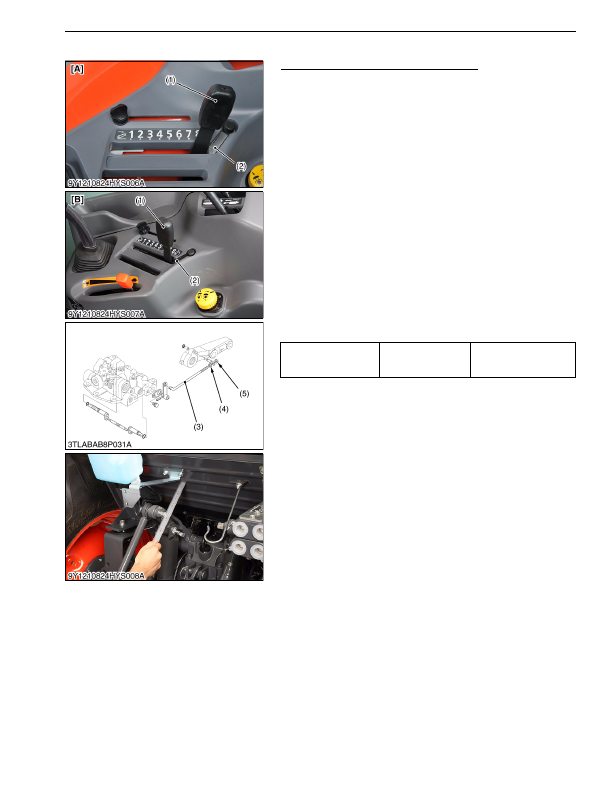
[4] POSITION CONTROL ROD
Adjusting Uppermost Position of Lift Arm
1. Set the position control lever (1) to the lowest position.
2. Start the engine, and after warming-up, set the engine speed at
the idling.
3. Move the position control lever (1) to the uppermost position.
[Contact to the position control lever stopper (2).]
4. While pulling the feedback rod to the rear, turn the adjusting nut
(4) clockwise until the relief valve begins to be operated.
5. From the relief valve operating position, turn back the adjusting
nut (4) counterclockwise by 2 turns.
6. Tighten the lock nut (5).
7. Set the engine speed at the maximum.
8. Move the position control lever (1) to the lowest position and
uppermost position to check the relief valve does not operate.
9. Set the position control lever (1) to the uppermost position, then
move the lift arm to the upper end by hand and measure the free
play.
10. If the measurement is not within the factory specifications,
adjust the position control feedback rod setting length.
• To reduce lift arm free play →
Shorten the position control feedback rod setting length.
• To increase lift arm free play →
Lengthen the position control feedback rod setting length.
9Y1210824HYS0010US0
Lift arm free play at
maximum raising
position
Factory specification
10 to 15 mm
0.39 to 0.59 in.
(1) Position Control Lever
(2) Stopper
(3) Position Control Feedback Rod
(4) Adjusting Nut
(5) Lock Nut
[A] ROPS Type
[B] CABIN Type
KiSC issued 03, 2016 A
Detailed Information for Kubota L3560 Owners Manual
Lists of information found in Kubota L3560 Owners Manual - Page 566
- 1. Set the position control lever (1) to the lowest position.
- 2. Start the engine, and after warming-up, set the engine speed at the idling.
- 3. Move the position control lever (1) to the uppermost position.
- 4. While pulling the feedback rod to the rear, turn the adjusting nut (4) clockwise until the relief valve begins to be operated.
- 5. From the relief valve operating position, turn back the adjusting nut (4) counterclockwise by 2 turns.
- 6. Tighten the lock nut (5).
- 7. Set the engine speed at the maximum.
- 8. Move the position control lever (1) to the lowest position and uppermost position to check the relief valve does not operate.
- 9. Set the position control lever (1) to the uppermost position, then move the lift arm to the upper end by hand and measure the free play.
- To reduce lift arm free play → Shorten the position control feedback rod setting length.
- To increase lift arm free play → Lengthen the position control feedback rod setting length.