[2] GLIDE SHIFT TRANSMISSION; (1) Clutch Housing; Differential Side Gear- Page 397
Kubota L3560 Owners Manual
Table of Contents
TRANSMISSION
L3560, L4060, L4760, L5060, L5460, L6060, WSM
3-S78
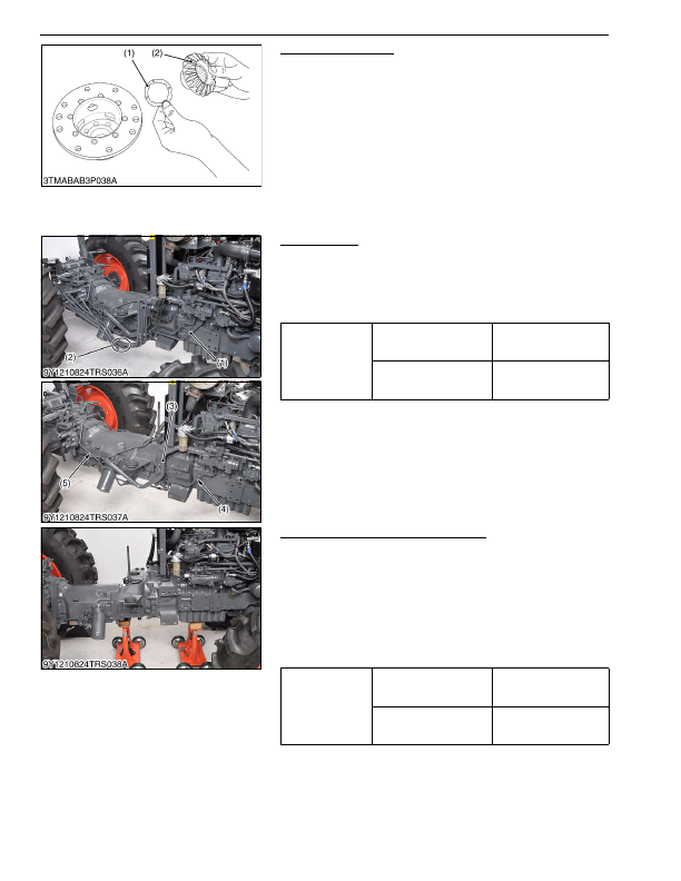
Differential Side Gear
1. Remove the differential side gear (2) and differential side gear
washer (1).
(When reassembling)
• Check the thrust and bearing surface of both differential side
gears (2). If they are worn or damaged, bores in the differential
case may also be damaged. Be sure to replace their parts.
9Y1210824TRS0049US0
[2] GLIDE SHIFT TRANSMISSION
(1) Clutch Housing
Hydraulic Pipe
1. Remove the front loader pipes (2) and main delivery pipe (1).
2. Remove the left and right brake rods.
3. Disconnect the suction pipe (3).
4. Remove the GST delivery pipe (5) and PTO delivery pipe (4).
(When reassembling)
9Y1210824TRS0052US0
Separating Engine and Clutch Housing
1. Place the disassembling stands under the engine and clutch
housing.
2. Remove the engine and clutch housing mounting screws and
nuts.
3. Separate the engine and clutch housing.
(When reassembling)
• Apply grease to the spline of clutch shaft.
• Apply liquid gasket (Three Bond 1211 or equivalent) to joint face
of the flywheel housing and clutch housing.
9Y1210824TRS0053US0
(1) Differential Side Gear Washer
(2) Differential Side Gear
Tightening torque
Joint bolt for main delivery
pipe
118 to 137 N·m
12.0 to 14.0 kgf·m
86.8 to 101 lbf·ft
Joint bolt for PTO delivery
pipe
35 to 39 N·m
3.5 to 4.0 kgf·m
26 to 28 lbf·ft
(1) Main Delivery Pipe
(2) Front Loader Pipe
(3) Suction Pipe
(4) PTO Delivery Pipe
(5) GST Delivery Pipe
Tightening torque
Engine and clutch housing
mounting screw
78 to 90 N·m
7.9 to 9.2 kgf·m
58 to 66 lbf·ft
Engine and clutch housing
mounting nut
103 to 117 N·m
10.5 to 12.0 kgf·m
76.0 to 86.7 lbf·ft
KiSC issued 03, 2016 A
Detailed Information for Kubota L3560 Owners Manual
Lists of information found in Kubota L3560 Owners Manual - Page 397
- 1. Remove the differential side gear (2) and differential side gear washer (1).
- 1. Remove the front loader pipes (2) and main delivery pipe (1).
- 2. Remove the left and right brake rods.
- 3. Disconnect the suction pipe (3).
- 4. Remove the GST delivery pipe (5) and PTO delivery pipe (4).
- 1. Place the disassembling stands under the engine and clutch housing.
- 2. Remove the engine and clutch housing mounting screws and nuts.
- 3. Separate the engine and clutch housing.
- 12.0 to 14.
- 86.8 to 101 lbf·ft Joint bolt for PTO delivery pipe 35 to 39 N·m 3.
- 4.0 kgf·m 26 to 28 lbf·ft (1) Main Delivery Pipe (2) Front Loader Pipe (3) Suction Pipe (4) PTO Delivery Pipe (5) GST Delivery Pipe Tightening torque Engine and clutch housing mounting screw 78 to 90 N·m 7.
- 9.2 kgf·m 58 to 66 lbf·ft Engine and clutch housing mounting nut 103 to 117 N·m 10.
- 12.0 kgf·m 76.
- Check the thrust and bearing surface of both differential side gears (2).
- Apply grease to the spline of clutch shaft.
- Apply liquid gasket (Three Bond 1211 or equivalent) to joint face of the flywheel housing and clutch housing.