[3] ELECTRICAL CONTROL SYSTEM; (1) Electrical Control; H: Time- Page 286
Kubota L3560 Owners Manual
Table of Contents
TRANSMISSION
L3560, L4060, L4760, L5060, L5460, L6060, WSM
3-M10
[3] ELECTRICAL CONTROL SYSTEM
(1) Electrical Control
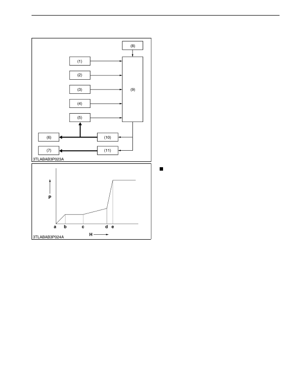
An electrical control of GST system is as follows.
1. Shift the GST lever and shuttle lever to desired
position.
2. The output voltage of selected gear shift position is
output to microcomputer of the main ECU by lever
sensor.
3. The main ECU detects the gear shift position with
GST lever sensor and shuttle switch, and excites
various solenoid valves in accordance with selected
position.
4. When the desired solenoid is excited, oil is sent to
the desired shift piston.
5. A pressure in the circuit is raised because the
movement of shift piston shuts the shift check pin.
When the pressure in the circuit reaches 0.49 MPa
(5 kgf/cm
2
, 71 psi), the pressure switch becomes
"ON"
.
6. By means of the pressure switch's
"ON"
, the main
ECU detects the present condition (traveling speed,
engine speed and oil temperature) from various
sensors, and pressure in the hydraulic clutch is
raised according to the respective condition.
NOTE
• By means of speed increasing, speed
decreasing, traveling speed, engine speed and
oil temperature, the indicated pressure period
from c to d is controlled at appropriate pressure
respectively.
7. A pressurizing to hydraulic clutch has been done
until it reaches the system pressure, and pressure in
the clutch is kept at this state.
9Y1210824TRM0015US0
(1) Oil Temperature Sensor
(2) Engine Tachometer Sensor
(3) Traveling Speed Sensor
(4) Shuttle Switch
(5) Pressure Switch
(6) Shift Piston
(7) Clutch Valve
(8) GST Lever Sensor
(9) Main ECU
(10) Solenoid Valves
(11) Proportional Reducing Valve
P:
Pressure
H: Time
a:
Starting of clutch engaging
b:
Low-pas pressure
c:
Starting of pressurized
c to d: Specified pressure from
Main ECU
e:
Gear shifting completion
KiSC issued 03, 2016 A
Detailed Information for Kubota L3560 Owners Manual
Lists of information found in Kubota L3560 Owners Manual - Page 286
- 1. Shift the GST lever and shuttle lever to desired position.
- 2. The output voltage of selected gear shift position is output to microcomputer of the main ECU by lever sensor.
- 3. The main ECU detects the gear shift position with GST lever sensor and shuttle switch, and excites various solenoid valves in accordance with selected position.
- 4. When the desired solenoid is excited, oil is sent to the desired shift piston.
- 5. A pressure in the circuit is raised because the movement of shift piston shuts the shift check pin.
- 6. By means of the pressure switch's "ON" , the main ECU detects the present condition (traveling speed, engine speed and oil temperature) from various sensors, and pressure in the hydraulic clutch is raised according to the respective condition.
- 7. A pressurizing to hydraulic clutch has been done until it reaches the system pressure, and pressure in the clutch is kept at this state.
- By means of speed increasing, speed decreasing, traveling speed, engine speed and oil temperature, the indicated pressure period from c to d is controlled at appropriate pressure respectively.