[5] CYLINDER HEAD AND VALVES; Boost Sensor; Cylinder Head Cover and Glow Plug- Page 203
Kubota L3560 Owners Manual
Table of Contents
ENGINE
L3560, L4060, L4760, L5060, L5460, L6060, WSM
1-S56
Boost Sensor
IMPORTANT
• Be careful not to damage the sensor when removing the
boost sensor.
1. Remove the boost sensor mounting screw (1).
2. Remove the boost sensor (2).
(When reassembling)
• Replace the O-ring with new ones.
9Y1210824ENS0037US0
[5] CYLINDER HEAD AND VALVES
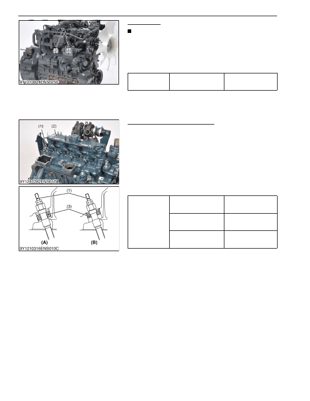
Cylinder Head Cover and Glow Plug
1. Remove the glow lead and the glow plugs (1).
2. Remove the cylinder head cover (2).
(When reassembling)
• Check to see that the cylinder head cover gasket is not
detective.
• Tighten the head cover mounting screws to specified torque.
• Replace the gasket of cylinder head cover with a new one.
• Adjust the direction of the ditch to the terminal side when the
seal (3) is installed in the glow plug (1).
• After installing the glow plug (1), make sure that the seal (3) was
set to the specified position.
9Y1210824ENS0038US0
Tightening torque
Boost sensor mounting
screw
0.98 to 1.7 N·m
0.10 to 0.18 kgf·m
0.73 to 1.3 lbf·ft
(1) Boost Sensor Mounting Screw
(2) Boost Sensor
Tightening torque
Cylinder head cover screw
6.86 to 11.3 N·m
0.700 to 1.15 kgf·m
5.06 to 8.33 lbf·ft
Glow lead mounting nut
0.98 to 1.7 N·m
0.10 to 0.18 kgf·m
0.73 to 1.3 lbf·ft
Glow plug
15 to 19 N·m
1.5 to 2.0 kgf·m
11 to 14 lbf·ft
(1) Glow Plug
(2) Cylinder Head Cover
(3) Seal
(A) Good
(B) Bad
KiSC issued 03, 2016 A
Detailed Information for Kubota L3560 Owners Manual
Lists of information found in Kubota L3560 Owners Manual - Page 203
- 1. Remove the boost sensor mounting screw (1).
- 2. Remove the boost sensor (2).
- 1. Remove the glow lead and the glow plugs (1).
- 2. Remove the cylinder head cover (2).
- 1.7 N·m 0.
- 1.3 lbf·ft (1) Boost Sensor Mounting Screw (2) Boost Sensor Tightening torque Cylinder head cover screw 6.
- 11.3 N·m 0.
- 1.15 kgf·m 5.
- 8.33 lbf·ft Glow lead mounting nut 0.
- 1.7 N·m 0.
- 1.3 lbf·ft Glow plug 15 to 19 N·m 1.
- Be careful not to damage the sensor when removing the boost sensor.
- Replace the O-ring with new ones.
- Check to see that the cylinder head cover gasket is not detective.
- Tighten the head cover mounting screws to specified torque.
- Replace the gasket of cylinder head cover with a new one.
- Adjust the direction of the ditch to the terminal side when the seal (3) is installed in the glow plug (1).
- After installing the glow plug (1), make sure that the seal (3) was set to the specified position.