5. CHECKING AND CHARGING REFRIGERANT CYCLE; [1] CHECKING WITH MANIFOLD GAUGE; Normal Operating- Page 756
Kubota L3560 Owners Manual
Table of Contents
CABIN
L3560, L4060, L4760, L5060, L5460, L6060, WSM
10-S13
5. CHECKING AND CHARGING REFRIGERANT
CYCLE
[1] CHECKING WITH MANIFOLD GAUGE
IMPORTANT
• The gauge indications described in the following testing are those taken under the same condition, so it
should be noted that the gauge readings will differs somewhat with the ambient conditions.
Condition
• Ambient temperature: 30 to 35 °C (86 to 95 °F)
• Engine speed: Approx. 1500 min
-1
(rpm)
• Temperature control lever: Maximum cooling position
• Air-Conditioner switch:
ON
• Blower switch:
HI
position
9Y1210824CAS0030US0
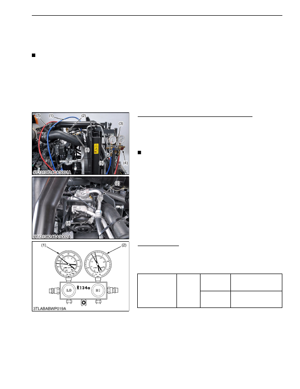
Manifold Gauge Connecting and Test Preparation
1. Close the manifold gauge
HI
and
LO
pressure side valve (4), (5)
tightly.
2. Connect the charging hose (7) (red) to the
HI
pressure side
charging valve (2) and connect the charging hose (1) (blue) to
the
LO
pressure side charging valve (6).
NOTE
• Be sure to drive out the air in the charging hoses at the
manifold gauge connection end by using the refrigerant
pressure in the refrigerating cycle.
3. Start the engine and set at approx. 1500 min
-1
(rpm).
4. Turn on the A/C switch and set the temperature control lever to
maximum cooling
position.
5. Set the blower switch to
HI
position.
9Y1210824CAS0031US0
Normal Operating
If the refrigerating cycle is operating normally, the reading at the
LO
pressure side (1) should be generally by around 0.15 to 0.2 MPa
(1.5 to 2.0 kgf/cm
2
, 21 to 28 psi) and that at the
HI
pressure side (2)
around 1.27 to 1.66 MPa (13 to 17 kgf/cm
2
, 185 to 242 psi).
9Y1210824CAS0032US0
(1) Charging Hose (Blue)
(2)
HI
Pressure Side Charging Valve
(3) Manifold Gauge
(4)
HI
Pressure Side Valve
(5)
LO
Pressure Side Valve
(6)
LO
Pressure Side Charging Valve
(7) Charging Hose (Red)
Gas pressure
Factory
specifica-
tion
Low pressure
side
0.15 to 0.20 MPa
1.5 to 2.0 kgf/cm
2
21 to 28 psi
High pressure
side
1.27 to 1.66 MPa
13 to 17 kgf/cm
2
185 to 242 psi
(1)
LO
Pressure Side
(2)
HI
Pressure Side
KiSC issued 03, 2016 A
Detailed Information for Kubota L3560 Owners Manual
Lists of information found in Kubota L3560 Owners Manual - Page 756
- 5. CHECKING AND CHARGING REFRIGERANT CYCLE [1] CHECKING WITH MANIFOLD GAUGE IMPORTANT • The gauge indications described in the following testing are those taken under the same condition, so it should be noted that the gauge readings will differs somewhat with the ambient conditions.
- 1. Close the manifold gauge HI and LO pressure side valve (4), (5) tightly.
- 2. Connect the charging hose (7) (red) to the HI pressure side charging valve (2) and connect the charging hose (1) (blue) to the LO pressure side charging valve (6).
- 3. Start the engine and set at approx.
- 4. Turn on the A/C switch and set the temperature control lever to maximum cooling position.
- 5. Set the blower switch to HI position.
- 1.5 to 2.
- 1.27 to 1.
- 1.5 to 2.
- 1.27 to 1.
- The gauge indications described in the following testing are those taken under the same condition, so it should be noted that the gauge readings will differs somewhat with the ambient conditions.
- Ambient temperature: 30 to 35 °C (86 to 95 °F) • Engine speed: Approx.
- Temperature control lever: Maximum cooling position • Air-Conditioner switch: ON • Blower switch: HI position 9Y1210824CAS0030US0 Manifold Gauge Connecting and Test Preparation 1.
- Be sure to drive out the air in the charging hoses at the manifold gauge connection end by using the refrigerant pressure in the refrigerating cycle.