[2] SHIFT LINKAGE MECHANISM; (1) Main Gear Shift Lever; (2) Shuttle Lever- Page 282
Kubota L3560 Owners Manual
Table of Contents
TRANSMISSION
L3560, L4060, L4760, L5060, L5460, L6060, WSM
3-M6
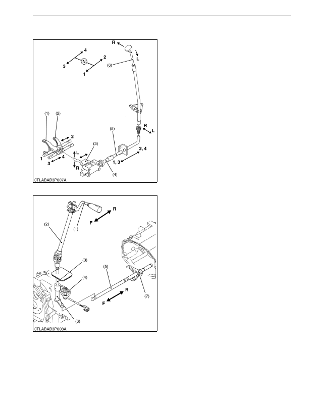
[2] SHIFT LINKAGE MECHANISM
(1) Main Gear Shift Lever
The links are connected from the shift lever (6) to the
shift forks (1), (2) as shown in the figure. Each speed
from the 1st to 4th can be changed by a single shift lever
(6).
When the shift lever (6) is moved to the left, the shift
arm (3) is engaged with the 1-2 shift fork (1), allowing the
operator to change the 1st or the 2nd speed.
When the shift lever (6) is moved to the right, the shift
arm (3) is engaged with the 3-4 shift fork (2), allowing the
operator to change the 3rd or the 4th speed.
9Y1210824TRM0009US0
(2) Shuttle Lever
The links are connected from the shift lever (1) to the
shift fork (7) as shown in the figure.
When the shift lever (1) is moved to the
"F"
side, the
shift fork (7) is moved toward the
"F"
side, allowing the
operator to shift to forward by means of the shuttle
universal joint (2), shuttle shift shaft (3), shift arm (6), and
shuttle fork rod (5).
When the shift lever (1) is moved to the
"R"
side, the
shift fork (7) is shifted to reverse position.
9Y1210824TRM0010US0
(1) 1-2 Shift Fork
(2) 3-4 Shift Fork
(3) Shift Arm
(4) Shift Rod 1
(5) Shift Rod 2
(6) Main Gear Shift Lever
R: Right Movement
L:
Left Movement
1:
1st Shift
2:
2nd Shift
3:
3rd Shift
4:
4th Shift
(1) Shuttle Shift Lever
(2) Shuttle Universal Joint
(3) Shuttle Shift Shaft
(4) Shuttle Switch
(5) Shuttle Fork Rod
(6) Shift Arm
(7) Shift Fork
F:
Forward Shift
R: Reverse Shift
KiSC issued 03, 2016 A