A: Chamber A; Pump Port; C1: Cylinder Port 1- Page 538
Kubota L3560 Owners Manual
Table of Contents
HYDRAULIC SYSTEM
L3560, L4060, L4760, L5060, L5460, L6060, WSM
8-M9
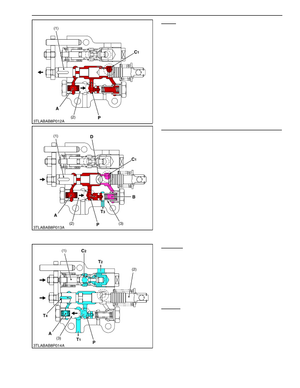
Lifting
When the control lever is moved to
"LIFT"
position,
spool (1) is pushed by the spool operating lever, forming
a circuit with the
P
port and chamber
A
.
The pressurized oil thus flows into the chamber
A
and closes unload poppet 1 (2).
The oil from
C1
port flows into hydraulic cylinder
through check valve in the rear hydraulic block to lift the
implement.
9Y1210824HYM0010US0
Lifting to Neutral (Acting the shockless mechanism)
In returning from Lifting to Neutral, the spool (1) is
pushed back to the arrow-mark direction. When the
Neutral
position comes near, the groove part
D
of the
spool (1) makes the pressure difference at the
P
port and
C1
port. Therefore, the check valve in the rear hydraulic
block gradually closes, and absorbs any shock at lifting
stop. In that case, since oil is remained in the chamber
A
of the unload poppet 1 (2) and closes. However, the
unload poppet 2 (3) opens because of low pressure in
chamber
B
, and then the oil from the pump returns to the
transmission case through
T3
port until unload poppet 1
(2) opens.
9Y1210824HYM0011US0
Lowering
When the control lever is moved to
"DOWN"
position, spool (2) moves to arrow-mark direction, and
pushes the poppet 2 (1). It forms a circuit with the
C2
port
and
T2
port.
The oil in the hydraulic cylinder is forced out by the
weight of the implement, and returns to the tank through
the
C2
port and
T2
port, lowering the implement.
The pressurized oil at the
P
port pushes open unload
poppet 1 (3) and returns to tank from
T1
port.
Floating
When the control lever is moved all the way to the
bottom, spool (2) and poppet 2 (1) remain in the position
described for
"Lowering"
. The oil flows freely between
the hydraulic pump, hydraulic cylinder and tank.
9Y1210824HYM0012US0
(1) Spool
(2) Unload Poppet 1
A: Chamber A
P:
Pump Port
C1: Cylinder Port 1
(1) Spool
(2) Unload Poppet 1
(3) Unload Poppet 2
A: Chamber A
B: Chamber B
D: Groove
P:
Pump Port
C1: Cylinder Port 1
T3: Tank Port 3
(1) Poppet 2
(2) Spool
(3) Unload Poppet 1
A: Chamber A
P:
Pump Port
C2: Cylinder Port 2
T1: Tank Port 1
T2: Tank Port 2
T4: Tank Port 4
KiSC issued 03, 2016 A