PTO Connector and Electric Connector; Step and Floor Seat- Page 365
Kubota L3560 Owners Manual
Table of Contents
TRANSMISSION
L3560, L4060, L4760, L5060, L5460, L6060, WSM
3-S46
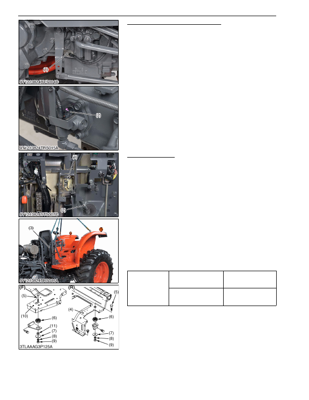
PTO Connector and Electric Connector
1. Disconnect the traveling speed sensor connector (1).
2. Disconnect the PTO connector (2).
9Y1210824TRS0007US0
Step and Floor Seat
1. Remove the universal joint bolt (1) and disconnect the steering
joint shaft 1 (2).
2. Disconnect the rear support plate (3).
3. Remove the step and floor seat mounting bolt and nut.
4. Lift up a little the step, fender, floor seat and panel frame as a
unit with the hoist.
5. Disconnect all the harness clips from the step, fenders and floor
seat.
6. Remove the harness.
7. Make sure that all the harnesses are removed.
8. Dismount the step, fender, floor seat and panel frame as a unit.
(When reassembling)
• Be sure to set the washers and rubber plates of the floor seat
and step mounting bolt at an original positions as shown in
figure.
• Before mounting the floor seat and step, be sure to set both the
shuttle lever rod and the shuttle arm to the neutral position, and
then connect the shuttle lever rod securely.
9Y1210824TRS0008US0
(1) Traveling Speed Sensor Connector (2) PTO Connector
Tightening torque
Step mounting bolt and nut
124 to 147 N·m
12.6 to 15.0 kgf·m
91.1 to 108 lbf·ft
Floor seat mounting bolt
and nut
196 to 225 N·m
20.0 to 23.0 kgf·m
145 to 166 lbf·ft
(1) Universal Joint Bolt
(2) Steering Joint Shaft 1
(3) Rear Support Plate
(4) Floor Seat
(5) Bolt
(6) Rubber Plate
(7) Washer
(8) Spring Washer
(9) Nut
(10) Step
(11) Washer (L.H. Only)
(F) Front Side
(R) Rear Side
KiSC issued 03, 2016 A
Detailed Information for Kubota L3560 Owners Manual
Lists of information found in Kubota L3560 Owners Manual - Page 365
- 1. Disconnect the traveling speed sensor connector (1).
- 2. Disconnect the PTO connector (2).
- 1. Remove the universal joint bolt (1) and disconnect the steering joint shaft 1 (2).
- 2. Disconnect the rear support plate (3).
- 3. Remove the step and floor seat mounting bolt and nut.
- 4. Lift up a little the step, fender, floor seat and panel frame as a unit with the hoist.
- 5. Disconnect all the harness clips from the step, fenders and floor seat.
- 6. Remove the harness.
- 7. Make sure that all the harnesses are removed.
- 8. Dismount the step, fender, floor seat and panel frame as a unit.
- 12.6 to 15.
- 91.1 to 108 lbf·ft Floor seat mounting bolt and nut 196 to 225 N·m 20.
- 23.0 kgf·m 145 to 166 lbf·ft (1) Universal Joint Bolt (2) Steering Joint Shaft 1 (3) Rear Support Plate (4) Floor Seat (5) Bolt (6) Rubber Plate (7) Washer (8) Spring Washer (9) Nut (10) Step (11) Washer (L.
- Be sure to set the washers and rubber plates of the floor seat and step mounting bolt at an original positions as shown in figure.
- Before mounting the floor seat and step, be sure to set both the shuttle lever rod and the shuttle arm to the neutral position, and then connect the shuttle lever rod securely.