Valve Clearance; Adjustable Cylinder Location ; Valve Arrangement- Page 160
Kubota L3560 Owners Manual
Table of Contents
ENGINE
L3560, L4060, L4760, L5060, L5460, L6060, WSM
1-S13
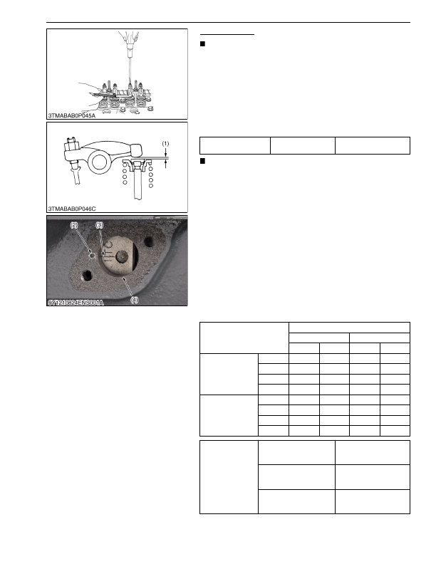
Valve Clearance
IMPORTANT
• You must examine and adjust the valve clearance when the
engine is cold.
1. Remove the head cover.
2. Align the
"1TC"
mark line (3) on the flywheel and timing mark
(2) on the housing. Make sure that the No.1 piston comes to the
compression or overlap top dead center.
3. Examine the subsequent valve clearance (1) at the mark "
"
with a feeler gauge.
4. If the clearance is out of the factory specifications, adjust with
the adjusting screw.
NOTE
• The "1TC" mark line on the flywheel is only for the No. 1
cylinder. There is no "TC" mark for the other cylinders.
• Align the "TC" mark with the center of timing mark (2) on
the flywheel-housing. No. 1 piston is on the top dead center
position at this time. Turn the flywheel 0.26 rad (15 °) to see
if the piston is at the compression top dead center or the
overlap position. Refer to the table below to adjust the
valve clearance (1) again. (The piston is at the compression
top dead center when both the IN. and EX. valves do not
move. The piston is at the overlap position when both the
valves move.)
• Turn the flywheel 6.28 rad (360 °) and align the "1TC" mark
line (3) with the timing mark (2) correctly. Adjust all the
other valve clearance if necessary.
• After you turn the flywheel counterclockwise 2 or 3 times,
examine the valve clearance (1) again.
• After you adjust the valve clearance (1), tighten the lock nut
of the adjusting screw.
9Y1210824ENS0005US0
Valve clearance
Factory specification
0.18 to 0.22 mm
0.0071 to 0.0086 in.
Adjustable Cylinder Location
of Piston
Valve Arrangement
3 Cylinder
4 Cylinder
IN.
EX.
IN.
EX.
When No. 1 piston
is at compression
top dead center
No. 1
No. 2
No. 3
No. 4
–
–
When No. 1 piston
is at overlap position
No. 1
No. 2
No. 3
No. 4
–
–
Tightening torque
Injector clamp screw
24 to 27 N·m
2.4 to 2.8 kgf·m
18 to 20 lbf·ft
Cylinder head cover screw
6.86 to 11.3 N·m
0.700 to 1.15 kgf·m
5.06 to 8.33 lbf·ft
Injection pipe retaining nut
24.5 to 29.4 N·m
2.50 to 2.99 kgf·m
18.1 to 21.6 lbf·ft
(1) Valve Clearance
(2) Timing Mark
(3) 1TC Mark Line
(4) Timing Window
KiSC issued 03, 2016 A
Detailed Information for Kubota L3560 Owners Manual
Lists of information found in Kubota L3560 Owners Manual - Page 160
- 1. Remove the head cover.
- 2. Align the "1TC" mark line (3) on the flywheel and timing mark (2) on the housing.
- 3. Examine the subsequent valve clearance (1) at the mark " " with a feeler gauge.
- 4. If the clearance is out of the factory specifications, adjust with the adjusting screw.
- 6.28 rad (360 °) and align the "1TC" mark line (3) with the timing mark (2) correctly.
- 2.4 to 2.
- 6.86 to 11.
- 1.15 kgf·m 5.
- 8.33 lbf·ft Injection pipe retaining nut 24.
- 29.4 N·m 2.
- 2.99 kgf·m 18.
- You must examine and adjust the valve clearance when the engine is cold.
- The "1TC" mark line on the flywheel is only for the No.
- Align the "TC" mark with the center of timing mark (2) on the flywheel-housing.
- Turn the flywheel 6.
- After you turn the flywheel counterclockwise 2 or 3 times, examine the valve clearance (1) again.
- After you adjust the valve clearance (1), tighten the lock nut of the adjusting screw.