Gear Case; Crankshaft Oil Slinger; Idle Gear (D1803-CR-E4)- Page 211
Kubota L3560 Owners Manual
Table of Contents
ENGINE
L3560, L4060, L4760, L5060, L5460, L6060, WSM
1-S64
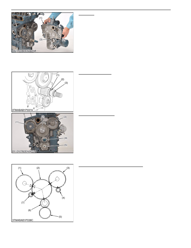
Gear Case
1. Remove the hour meter gear case (if attached).
2. Remove the gear case (1).
3. Remove the O-rings (2).
(When reassembling)
• Replace the gear case gasket and O-rings (2).
• Replace the hour meter gear case gasket with a new one.
• Make sure that there are 4 O-rings (2) in the gear case (1).
• Apply a thin layer of engine oil to the oil seal.
Then install the oil seal not to come off the lip.
• Before you install the gear case gasket, apply an adhesive that
does not become dry.
9Y1210824ENS0050US0
Crankshaft Oil Slinger
1. Remove the crankshaft collar (3).
2. Remove the O-ring (2).
3. Remove the crankshaft oil slinger (1).
(When reassembling)
• Attach the crankshaft collar (3) after you install the gear case to
the cylinder body.
9Y1210824ENS0051US0
Idle Gear (D1803-CR-E4)
1. Remove the external snap ring.
2. Remove the idle gear collar.
3. Remove the idle gear (2).
(When reassembling)
• Align each gear with its mark.
– Idle gear (2) and crank gear (4)
– Idle gear (2) and cam gear (3)
– Idle gear (2) and fuel supply pump gear (1)
9Y1210824ENS0052US0
Idle Gear (V2403-CR-E4 and V2403-CR-TE4)
1. Remove the external snap ring.
2. Remove the idle gear collar.
3. Remove the idle gear (2).
(When reassembling)
• Check to see each gear is aligned with its aligning mark:
– Idle gear (2) and crank gear (6), cam gear (3) and balancer
gear (4)
– Cam gear (3) and idle gear (2)
– Idle gear (2) and fuel supply pump gear (1)
– Idle gear (2) and balancer gear (7)
9Y1210824ENS0123US0
(1) Gear Case
(2) O-ring
(3) Oil Seal
(1) Crankshaft Oil Slinger
(2) O-ring
(3) Crankshaft Collar
(1) Fuel Supply Pump Gear
(2) Idle Gear
(3) Cam Gear
(4) Crank Gear
(5) Oil Pump Drive Gear
(1) Fuel Supply Pump Gear
(2) Idle Gear
(3) Cam Gear
(4) Balancer Gear
(5) Oil Pump Drive Gear
(6) Crank Gear
(7) Balancer Gear
KiSC issued 03, 2016 A
Detailed Information for Kubota L3560 Owners Manual
Lists of information found in Kubota L3560 Owners Manual - Page 211
- 1. Remove the hour meter gear case (if attached).
- 2. Remove the gear case (1).
- 3. Remove the O-rings (2).
- 1. Remove the crankshaft collar (3).
- 2. Remove the O-ring (2).
- 3. Remove the crankshaft oil slinger (1).
- 1. Remove the external snap ring.
- 2. Remove the idle gear collar.
- 3. Remove the idle gear (2).
- 1. Remove the external snap ring.
- 2. Remove the idle gear collar.
- 3. Remove the idle gear (2).
- Replace the gear case gasket and O-rings (2).
- Replace the hour meter gear case gasket with a new one.
- Make sure that there are 4 O-rings (2) in the gear case (1).
- Apply a thin layer of engine oil to the oil seal.
- Before you install the gear case gasket, apply an adhesive that does not become dry.
- Attach the crankshaft collar (3) after you install the gear case to the cylinder body.
- Align each gear with its mark.