Fuel Camshaft; Camshaft and Balancer Shaft (V2403-CR-E4 and- Page 212
Kubota L3560 Owners Manual
Table of Contents
ENGINE
L3560, L4060, L4760, L5060, L5460, L6060, WSM
1-S65
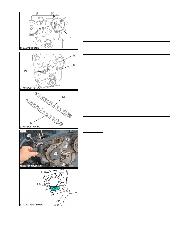
Camshaft (D1803-CR-E4)
1. Remove the camshaft set screws (1) and pull out the camshaft
(2).
(When reassembling)
• When you install the idle gear, align the marks on the gears.
9Y1210824ENS0053US0
Camshaft and Balancer Shaft (V2403-CR-E4 and
V2403-CR-TE4)
1. Remove the camshaft set bolts and draw out the camshaft (1).
2. Remove the balancer shaft 1 (2) set bolts and draw out the
balancer shaft 1 (2).
3. Remove the balancer shaft 2 (3) set bolts and draw out the
balancer shaft 2 (3).
(When reassembling)
• When install the balancer shaft 1 and 2, be sure to place the 4th
cylinders piston at the top dead center in compression then,
align all mating marks on each gear to assemble the timing
gears, set the idle gear last.
9Y1210824ENS0124US0
Fuel Camshaft
1. Remove the fuel feed pump.
2. Remove the fuel camshaft stopper (1).
3. Pull out the fuel camshaft assembly (2).
(When reassembling)
• After attaching the fuel camshaft, store oil in the pump room as
shown in drawing on the left.
• Recommended oil amount about 110 cc.
9Y1210824ENS0054US0
Tightening torque
Camshaft set screw
24 to 27 N·m
2.4 to 2.8 kgf·m
18 to 20 lbf·ft
(1) Camshaft Set Screw
(2) Camshaft
Tightening torque
Camshaft set bolt
24 to 27 N·m
2.4 to 2.8 kgf·m
18 to 20 lbf·ft
Balancer shaft set bolt
24 to 27 N·m
2.4 to 2.8 kgf·m
18 to 20 lbf·ft
(1) Camshaft
(2) Balancer Shaft 1
(3) Balancer Shaft 2
(1) Fuel Camshaft Stopper
(2) Fuel Camshaft
(3) Oil
KiSC issued 03, 2016 A
Detailed Information for Kubota L3560 Owners Manual
Lists of information found in Kubota L3560 Owners Manual - Page 212
- 1. Remove the camshaft set screws (1) and pull out the camshaft (2).
- 1. Remove the camshaft set bolts and draw out the camshaft (1).
- 2. Remove the balancer shaft 1 (2) set bolts and draw out the balancer shaft 1 (2).
- 3. Remove the balancer shaft 2 (3) set bolts and draw out the balancer shaft 2 (3).
- 1. Remove the fuel feed pump.
- 2. Remove the fuel camshaft stopper (1).
- 3. Pull out the fuel camshaft assembly (2).
- 2.4 to 2.
- 2.4 to 2.
- 2.4 to 2.
- When you install the idle gear, align the marks on the gears.
- When install the balancer shaft 1 and 2, be sure to place the 4th cylinders piston at the top dead center in compression then, align all mating marks on each gear to assemble the timing gears, set the idle gear last.
- After attaching the fuel camshaft, store oil in the pump room as shown in drawing on the left.
- Recommended oil amount about 110 cc.