Adjust Front Axle Pivot; A: Clearance; vibration can occur causing vibration in the steering wheel.- Page 496
Kubota L3560 Owners Manual
Table of Contents
FRONT AXLE
L3560, L4060, L4760, L5060, L5460, L6060, WSM
6-S6
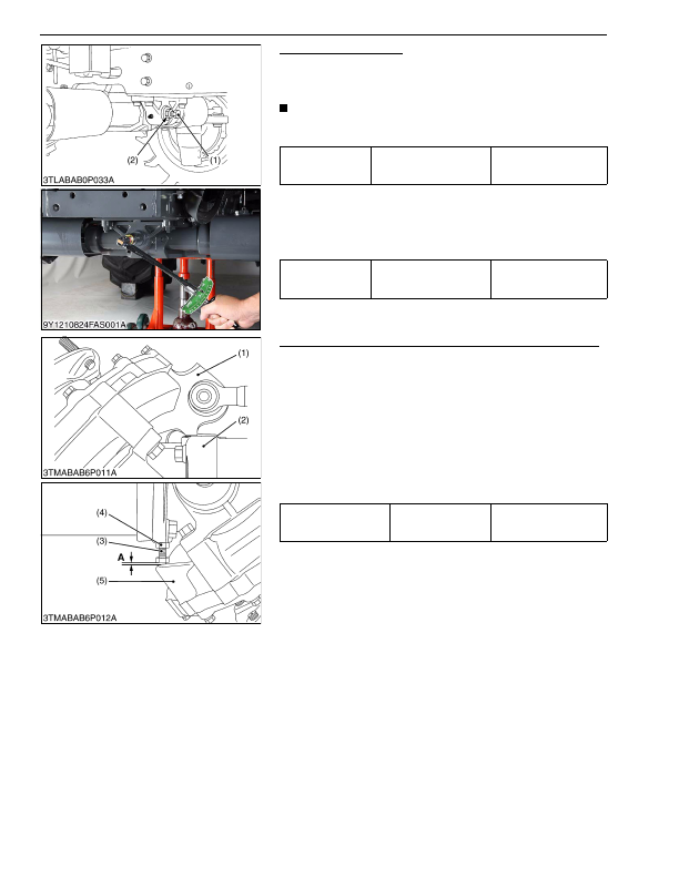
Adjust Front Axle Pivot
1. Loosen the lock nut (2), tighten the adjusting screw (1) all the
way, and then loosen the adjusting screw (1) by 1/6 turn.
2. Retighten the lock nut (2).
NOTE
• If the axle pivot pin adjustment is not correct, front wheel
vibration can occur causing vibration in the steering wheel.
(Reference)
• Measure the adjusting screw tightening torque.
• If tightening torque is not within the factory specifications, adjust
the adjusting screw (1).
• After adjustment, tighten the lock nut (2) firmly.
9Y1210824FAS0007US0
Front Wheel Steering Angle (L4760, L5060, L5460 and L6060)
1. Inflate the tires to the specified pressure.
2. Steer the wheels to the extreme right until the front gear case
(1) contacts with the bevel gear case (2) at right hand side of the
front axle.
3. If the front gear case (1) can not be contacted with the bevel
gear case (2), shorten the length of stopper (3).
4. Keeping the front gear case (1) contact with the bevel gear case
(2), make a specified clearance
"A"
as shown in the lower table.
5. After adjustment, secure the stopper with the lock nut (4).
6. For adjusting the left steering angle, perform the same
procedure as mentioned in right steering angle.
9Y1210824FAS0008US0
Tightening torque
Lock nut
59 to 98 N·m
6.0 to 10 kgf·m
44 to 72 lbf·ft
Tightening torque
Front axle adjusting screw
20 to 29 N·m
2.0 to 3.0 kgf·m
15 to 21 lbf·ft
(1) Adjusting Screw
(2) Lock Nut
Clearance
"A"
between
bevel gear case and
stopper
Factory specification
1.0 to 3.0 mm
0.040 to 0.11 in.
(1) Front Gear Case
(2) Bevel Gear Case
(3) Stopper
(4) Lock Nut
(5) Front Gear Case
A: Clearance
KiSC issued 03, 2016 A
Detailed Information for Kubota L3560 Owners Manual
Lists of information found in Kubota L3560 Owners Manual - Page 496
- 1. Loosen the lock nut (2), tighten the adjusting screw (1) all the way, and then loosen the adjusting screw (1) by 1/6 turn.
- 2. Retighten the lock nut (2).
- 1. Inflate the tires to the specified pressure.
- 2. Steer the wheels to the extreme right until the front gear case (1) contacts with the bevel gear case (2) at right hand side of the front axle.
- 3. If the front gear case (1) can not be contacted with the bevel gear case (2), shorten the length of stopper (3).
- 4. Keeping the front gear case (1) contact with the bevel gear case (2), make a specified clearance "A" as shown in the lower table.
- 5. After adjustment, secure the stopper with the lock nut (4).
- 6. For adjusting the left steering angle, perform the same procedure as mentioned in right steering angle.
- 6.0 to 10 kgf·m 44 to 72 lbf·ft Tightening torque Front axle adjusting screw 20 to 29 N·m 2.
- 3.0 kgf·m 15 to 21 lbf·ft (1) Adjusting Screw (2) Lock Nut Clearance "A" between bevel gear case and stopper Factory specification 1.
- 3.0 mm 0.
- If the axle pivot pin adjustment is not correct, front wheel vibration can occur causing vibration in the steering wheel.
- Measure the adjusting screw tightening torque.
- If tightening torque is not within the factory specifications, adjust the adjusting screw (1).
- After adjustment, tighten the lock nut (2) firmly.