(2) Disassembling Hydraulic Pump; Hydraulic Pump Assembly; Hydraulic Pump Running-In- Page 569
Kubota L3560 Owners Manual
Table of Contents
HYDRAULIC SYSTEM
L3560, L4060, L4760, L5060, L5460, L6060, WSM
8-S16
(2) Disassembling Hydraulic Pump
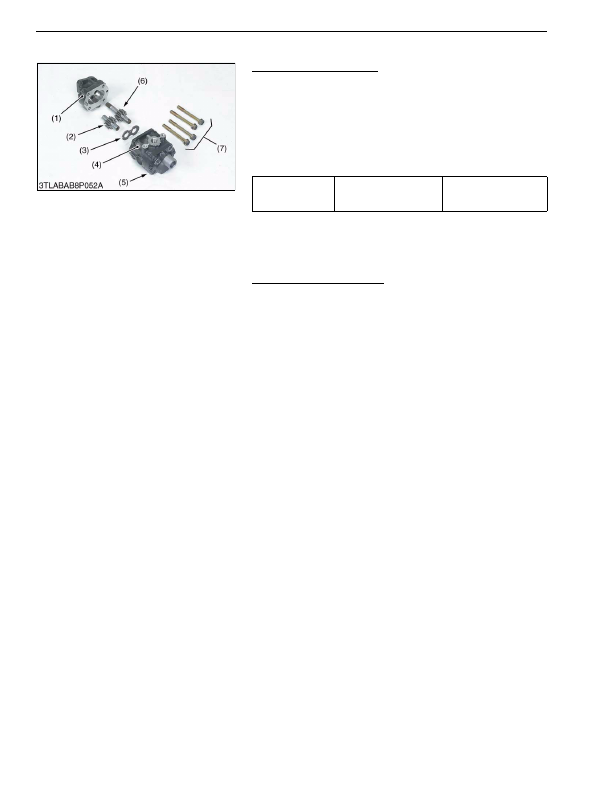
Hydraulic Pump Assembly
1. Remove the pump cover mounting screws (7).
2. Remove the drive gear (6), driven gear (2) and side plate (3)
from the casing.
(When reassembling)
• Be careful not to damage the gasket.
• Align the hole of the pump cover (5) and casing 2 (4).
• Install the side plate, noting its location and direction.
• Install the gears, noting its direction.
9Y1210824HYS0016US0
Hydraulic Pump Running-In
After reassembly, perform break-in operation in the following
manner, and check the pump for abnormality before use. If the
pump temperature should rise noticeably during running-in, recheck
should be performed.
1. Install the hydraulic pump to the tractor, and mount the suction
pipe and delivery pipe securely.
2. Set the engine speed at 1300 to 1500 min
-1
(rpm), and operate
the hydraulic pump at no load for about 10 minutes.
3. Set the engine speed at 2000 to 2200 min
-1
(rpm), and with the
hydraulic pump applied with 2.94 MPa (30.0 kgf/cm
2
, 426 psi) to
4.90 MPa (50.0 kgf/cm
2
, 711 psi) pressure, operate it for
approx. 15 minutes.
4. With the engine set to maximum speed, fully turn the steering
wheel to the left or right, then actuate the relief valve five times
for 25 seconds (one time 5 seconds).
9Y1210824HYS0017US0
Tightening torque
Pump cover mounting
screw
40 to 44 N·m
4.0 to 4.5 kgf·m
29 to 32 lbf·ft
(1) Casing 1
(2) Driven Gear
(3) Side Plate
(4) Casing 2
(5) Pump Cover
(6) Drive Gear
(7) Screw
KiSC issued 03, 2016 A
Detailed Information for Kubota L3560 Owners Manual
Lists of information found in Kubota L3560 Owners Manual - Page 569
- 1. Remove the pump cover mounting screws (7).
- 2. Remove the drive gear (6), driven gear (2) and side plate (3) from the casing.
- 1. Install the hydraulic pump to the tractor, and mount the suction pipe and delivery pipe securely.
- 2. Set the engine speed at 1300 to 1500 min -1 (rpm), and operate the hydraulic pump at no load for about 10 minutes.
- 3. Set the engine speed at 2000 to 2200 min -1 (rpm), and with the hydraulic pump applied with 2.
- 4.90 MPa (50.
- 4. With the engine set to maximum speed, fully turn the steering wheel to the left or right, then actuate the relief valve five times for 25 seconds (one time 5 seconds).
- 4.0 to 4.
- Be careful not to damage the gasket.
- Align the hole of the pump cover (5) and casing 2 (4).
- Install the side plate, noting its location and direction.
- Install the gears, noting its direction.