Suction Control Valve (SCV); is needed to replace.; to the voltage based on the magnetic force- Page 125
Kubota L3560 Owners Manual
Table of Contents
ENGINE
L3560, L4060, L4760, L5060, L5460, L6060, WSM
1-M10
Suction Control Valve (SCV)
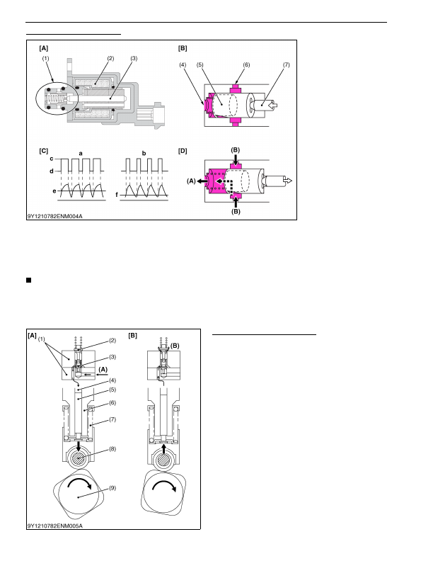
The suction control valve (SCV) is a proportional control valve that adjusts the amount of fuel delivered from the
fuel pump to achieve the fuel pressure requested by the engine, has a function of delivering to the pressurizing part,
and is made up of a piston (5), cylinder (6), armature (3), and solenoid (2) etc.
The SCV is a linear solenoid type electromagnetic valve and the engine ECU controls the time the solenoid is
electrified (duty ratio control). When current flows through the solenoid, the armature moves based on the duty ratio
and pushes on the cylinder and fuel flow changes based on position of the cylinder enabling suitable fuel flow.
NOTE
• Since the suction control valve (SCV) has not been adopted as a part, replace the supply pump when SCV
is needed to replace.
• Linear solenoid type: when voltage is applied to the coil, the moveable core moves linearly in proportion
to the voltage based on the magnetic force
9Y1210824ENM0013US0
Pressurizing Part (Pump Body)
The pressurizing part (pump body) applies pressure
to the fuel supplied from the suction control valve, has a
function of supplying fuel to the rail, and is made up of an
IO valve (1), plunger (5), plunger barrel (6), spring (7),
tappet (8), and pump housing etc.
The engine side fuel camshaft (9) rotates and during
the lowering stroke, the spring cause the plunger to
lower. An optimal amount of fuel adjusted by the suction
control valve is suctioned through the IO valve and into
the plunger chamber (4).
Rotation continues and during the lift stroke of the
cam the plunger rises, pressurizes the fuel, and supplies
it through the IO valve to the rail.
9Y1210824ENM0014US0
(1) Cylinder Part
(2) Solenoid
(3) Armature
(4) Discharge Port
(5) Piston
(6) Cylinder
(7) Suction Port
a: High Suction Volume
b: Low Suction Volume
c: ON
d: OFF
e: Large
f: Small
(A) To pressurizing section
(B) From fuel pump
[A] Suction Control Valve
[B] No delivery (current ON)
[C] When Solenoid is
Electrified
[D] Maximum delivery volume
(current OFF)
(1) IO Valve
(2) Outlet Valve
(3) Inlet Valve
(4) Plunger Chamber
(5) Plunger
(6) Plunger Barrel
(7) Spring
(8) Tappet
(9) Fuel Camshaft
(A) From suction control valve
(B) To rail
[A] Suction Stroke
[B] Compression Stroke
KiSC issued 03, 2016 A
Detailed Information for Kubota L3560 Owners Manual
Lists of information found in Kubota L3560 Owners Manual - Page 125
- Since the suction control valve (SCV) has not been adopted as a part, replace the supply pump when SCV is needed to replace.
- Linear solenoid type: when voltage is applied to the coil, the moveable core moves linearly in proportion to the voltage based on the magnetic force 9Y1210824ENM0013US0 Pressurizing Part (Pump Body) The pressurizing part (pump body) applies pressure to the fuel supplied from the suction control valve, has a function of supplying fuel to the rail, and is made up of an IO valve (1), plunger (5), plunger barrel (6), spring (7), tappet (8), and pump housing etc.