Injector Operation; No Injection; Injection Start- Page 130
Kubota L3560 Owners Manual
Table of Contents
ENGINE
L3560, L4060, L4760, L5060, L5460, L6060, WSM
1-M15
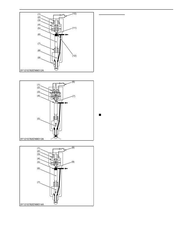
Injector Operation
No Injection
While the solenoid (2) is not electrified, the two way
electromagnetic valve (3) is pushed down by the valve
spring (1) and the discharge orifice (11) path is closed by
the valve ball (4). Here, fuel pressure is applied in the
control chamber (5) and to the bottom of the needle
valve (8) but based on the difference in projected net
area and the force of the nozzle spring (7), the needle
valve is pushed into the nozzle body (9) so fuel injection
is not performed.
9Y1210824ENM0021US0
Injection Start
When the solenoid (1) is electrified by the drive
circuit (6) the two way electromagnetic valve (2) is lifted
by an electromagnetic force and the valve ball (3) is lifted
by fuel pressure opening the discharge orifice (7). Here,
fuel inside the control chamber (4) passes through the
discharge orifice and flows to the fuel tank. As a result,
the needle valve (5) is pushed up based on fuel pressure
and fuel injection starts.
NOTE
• Longer electrification time of the solenoid leads
to increased amount of fuel injected.
9Y1210824ENM0022US0
Injection Complete
When electrification of the solenoid (2) by the drive
circuit (9) stops, the two way electromagnetic valve (3) is
pushed closed by the force of the valve spring (1) and
the discharge orifice (9) is closed by the valve ball (4). As
a result, fuel pressure in the control chamber (5) rises
and the needle valve (7) is pushed by the valve piston
(6).
9Y1210824ENM0023US0
(1) Valve Spring
(2) Solenoid
(3) Two Way Electromagnetic
Valve
(4) Valve Ball
(5) Control Chamber
(6) Valve Piston
(7) Nozzle Spring
(8) Needle Valve
(9) Nozzle Body
(10) Drive Circuit
(11) Discharge Orifice
(12) Suction Orifice
(1) Solenoid
(2) Two Way Electromagnetic
Valve
(3) Valve Ball
(4) Control Chamber
(5) Needle Valve
(6) Drive Circuit
(7) Discharge Orifice
(1) Valve Spring
(2) Solenoid
(3) Two Way Electromagnetic
Valve
(4) Valve Ball
(5) Control Chamber
(6) Valve Piston
(7) Needle Valve
(8) Drive Circuit
(9) Discharge Orifice
KiSC issued 03, 2016 A
Detailed Information for Kubota L3560 Owners Manual
Lists of information found in Kubota L3560 Owners Manual - Page 130
- Longer electrification time of the solenoid leads to increased amount of fuel injected.