(1) Engine ECU; (2) Sensor; Fuel Quantity Control- Page 133
Kubota L3560 Owners Manual
Table of Contents
ENGINE
L3560, L4060, L4760, L5060, L5460, L6060, WSM
1-M18
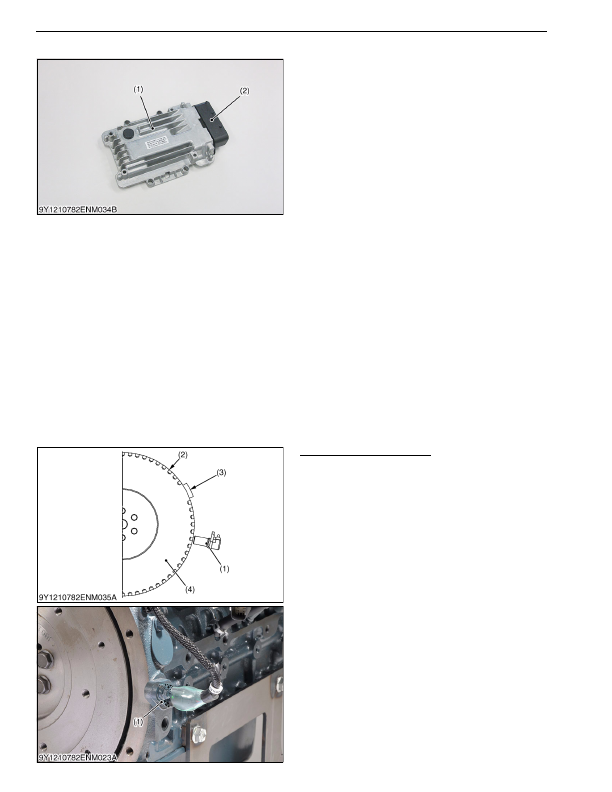
(1) Engine ECU
The engine ECU (1) controls the amount, timing,
mixture and pressure of fuel that is injected. The engine
ECU (1) operates each kind of control based on the
signals from each type of sensor.
The actuator for controlling the amount, timing and
mixture of fuel injection is the injector, while the actuator
for controlling fuel pressure is the supply pump.
Fuel Quantity Control
The amount of fuel to be injected is determined using
a basic injection amount, which is calculated based on
the state of the engine and driving conditions, with
corrections added for parameters such as water
temperature, intake air temperature, intake pressure,
etc.
Injection Timing Control
The ECU controls the timing for starting to energize
the injectors, first determining the timing for the main
injection and then setting the timing of other injections,
such as pilot injections.
Fuel Mixture Control
By conducting a pilot injection, the initial fuel mixture
is kept to a minimum, mitigating the explosive initial
combustion and reducing NOx and noise.
Fuel Pressure Control
The ECU calculates the set fuel injection pressure
based on the engine load (last injection amount and
engine RPM) and controls the amount the supply pump
supplies and the fuel pressure inside the rail.
9Y1210824ENM0029US0
(2) Sensor
Crankshaft Position Sensor
The crank position sensor (1) is mounted on the
flywheel housing and the sensor body uses a hall
element type.
When pulse holes (2) provided on the outer edge of
the flywheel (4) pass through the sensor, the internal
magnetic field changes and this is output to the engine
ECU.
Also, a no hole part (3) is provided in a part and this
detects the crank position each rotation and outputs this
to the engine ECU.
The engine ECU uses the signals to calculate the
crank angle and engine speed.
9Y1210824ENM0030US0
(1) Engine ECU
(2) ECU Connector
(1) Crankshaft Position Sensor
(2) Pulse Hole
(3) Part without a Hole
(4) Flywheel
KiSC issued 03, 2016 A