A: A Port; B: B Port; C: C Port- Page 302
Kubota L3560 Owners Manual
Table of Contents
TRANSMISSION
L3560, L4060, L4760, L5060, L5460, L6060, WSM
3-M26
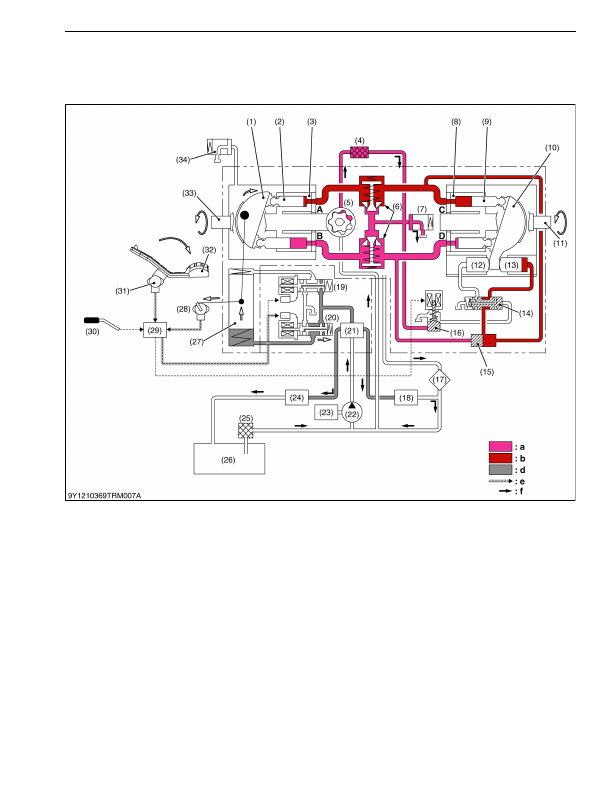
[B] Stage 2
When the pedal is pressed toward the forward side
[Tractor Condition]
HST pedal:
Forward
Position
Hi-Lo select lever:
Lo
When the HST pedal is pressed toward the forward side, signals from the HST pedal sensor are transmitted to
the ECU. Then the signals are transmitted from the ECU to the proportional control valve, which guide oil from the
regulator valve and moves the servo piston. With this, the swashplate on the pump side is tilted as shown in the
drawing. The speed of the motion and stroke of the servo piston are controlled by the ECU based on the motion of
the pedal.
9Y1210824TRM0033US0
(1) Pump Swashplate
(2) Pump Piston
(3) Pump Cylinder Block
(4) HST Filter
(5) Charge Pump
(6) Check and High Pressure
Relief Valve
(7) Charge Relief Valve
(8) Motor Cylinder Block
(9) Motor Piston
(10) Motor Swashplate
(11) Out Put Shaft (Motor Shaft)
(12) Piston H
(13) Piston L
(14) Hi-Lo Spool
(15) Spool (Pressure Selector)
(16) Hi-Lo Solenoid Valve
(17) Oil Cooler
(18) Power Steering Controller
(19) Proportional Valve (Reverse)
(20) Proportional Valve (Forward)
(21) Regulator Valve
(22) Hydraulic Pump
(23) Engine
(24) PTO Valve
(25) Filter
(26) Transmission Case
(27) Servo Piston
(28) Servo Position
(29) ECU
(30) Hi-Lo Selector Lever
(31) HST Pedal Sensor
(32) HST Pedal
(33) Input Shaft (Pump Shaft)
(34) Case Relief Valve
A: A Port
B: B Port
C: C Port
D: D Port
a:
Charge Pressure
b:
High Pressure
d:
Regulating Pressure
e:
Signal
f:
Oil Flow
KiSC issued 03, 2016 A