Forward Side; R: Reverse Side; Checking and Adjusting HST Neutral Position- Page 352
Kubota L3560 Owners Manual
Table of Contents
TRANSMISSION
L3560, L4060, L4760, L5060, L5460, L6060, WSM
3-S33
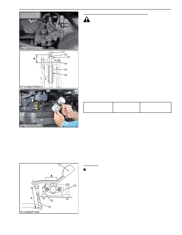
Checking and Adjusting HST Neutral Position
CAUTION
• Park the tractor on a flat place and keep all the levers at
neutral position.
• Jack up the engine tractor and bring it in the 2WD mode.
1. Fit the HST mechanism first and then exterior components until
the engine can get started.
2. Remove the hex. socket head plug from
F
and
R
ports.
3. Assemble adaptor
C
(07916-50371) and thread joint
(07916-50341) with the gasket between them.
4. Install the assembled adaptor
C
and thread joint
F
and
R
ports.
5. Measure the
F
and
R
HST charge pressures. Place 5 MPa
(50 kgf/cm
2
, 725 psi) gauges on the two spots in the photo.
6. Lift up the entire steps, as shown below, so that the piston can
be adjusted.
7. If any of the servo piston parts has been replaced, readjust the
HST neutral position, referring to the dimension
"A"
of the servo
piston adjusting screw (2).
8. Start the engine and measure the
F
and
R
charge pressures.
Now adjust the piston neutral position so that the
F
port side
pressure and the
R
port side one be the same. (Take the
measurement with the engine rpm at MAX.).
9. Finally lock the piston adjusting nut and fit the exterior
components.
Condition
• Engine speed
Maximum Speed
• Oil temperature
40 to 60 °C (104 to 140 °F)
(Reference)
• Dimension
"A"
: 19.4 mm (0.764 in.)
9Y1210824TRS0192US0
HST Pedal
NOTE
• When removing the HST pedal, do the following
adjustment.
1. Adjust the rod length
"L"
so that the face of the HST pedal
"A"
becomes horizontal.
2. After adjusting the HST pedal perform
"Mode K"
. (See page
(Reference)
• Rod length
"L"
: 109 mm (4.29 in.)
9Y1210824TRS0193US0
Differential pressure
F-R
Factory specification
−0.3 to +0.3 MPa
−3 to +3 kgf/cm
2
−40 to +40 psi
(1) Cap Nut
(2) Adjusting Screw
(3) Lock Nut
(4) Cover
(5) Servo Piston
(6) Spring
F:
Forward Side
R: Reverse Side
(1) HST Pedal
(2) Stopper Bolt (Forward)
(3) Stopper Bolt (Reverse)
(4) Rod
A: Face of HST Pedal
KiSC issued 03, 2016 A
Detailed Information for Kubota L3560 Owners Manual
Lists of information found in Kubota L3560 Owners Manual - Page 352
- 1. Fit the HST mechanism first and then exterior components until the engine can get started.
- 2. Remove the hex.
- 3. Assemble adaptor C (07916-50371) and thread joint (07916-50341) with the gasket between them.
- 4. Install the assembled adaptor C and thread joint F and R ports.
- 5. Measure the F and R HST charge pressures.
- 6. Lift up the entire steps, as shown below, so that the piston can be adjusted.
- 7. If any of the servo piston parts has been replaced, readjust the HST neutral position, referring to the dimension "A" of the servo piston adjusting screw (2).
- 8. Start the engine and measure the F and R charge pressures.
- 9. Finally lock the piston adjusting nut and fit the exterior components.
- 19.4 mm (0.
- 1. Adjust the rod length "L" so that the face of the HST pedal "A" becomes horizontal.
- 2. After adjusting the HST pedal perform "Mode K" .
- 27.) (Reference) • Rod length "L" : 109 mm (4.
- Park the tractor on a flat place and keep all the levers at neutral position.
- Jack up the engine tractor and bring it in the 2WD mode.
- Engine speed Maximum Speed • Oil temperature 40 to 60 °C (104 to 140 °F) (Reference) • Dimension "A" : 19.
- When removing the HST pedal, do the following adjustment.
- Rod length "L" : 109 mm (4.