Spiral Bevel Pinion Shaft; Backlash and Tooth Contact between Spiral Bevel Gear and- Page 446
Kubota L3560 Owners Manual
Table of Contents
TRANSMISSION
L3560, L4060, L4760, L5060, L5460, L6060, WSM
3-S127
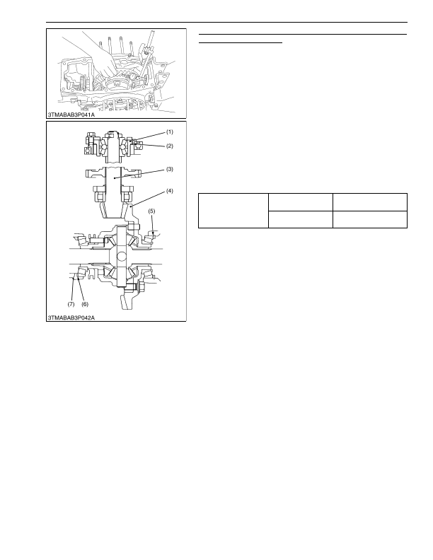
Backlash and Tooth Contact between Spiral Bevel Gear and
Spiral Bevel Pinion Shaft
1. Set the dial indicator (lever type) with its finger on the tooth
surface.
2. Measure the backlash by fixing the spiral bevel pinion shaft (3)
and moving the spiral bevel gear (4) by hand.
3. When the backlash is too large, decrease the number of shims
(6) in the side of the spiral bevel gear, and insert the shims (5)
of the same thickness as the removed ones to the opposite side.
When the backlash is too small, do the opposite way to increase
backlash.
4. Adjust the backlash periphery by repeating the above
procedure.
5. Apply red lead lightly over several teeth at three positions
equally spaced on the spiral bevel gear.
6. Turn the spiral bevel pinion shaft, while pressing a wooden
piece against the periphery on the spiral bevel gear.
7. Check the tooth contact. If not proper, adjust according to the
instructions below.
(Reference)
• Thickness of shims (2)
0.1 mm (0.004 in.)
0.2 mm (0.008 in.)
0.5 mm (0.02 in.)
• Thickness of shims (5)
0.4 mm (0.016 in.)
0.5 mm (0.020 in.)
0.6 mm (0.024 in.)
0.7 mm (0.028 in.)
0.8 mm (0.031 in.)
0.9 mm (0.035 in.)
1.0 mm (0.039 in.)
1.2 mm (0.047 in.)
1.4 mm (0.055 in.)
• Thickness of shims (6)
0.4 mm (0.016 in.)
0.6 mm (0.024 in.)
0.8 mm (0.031 in.)
1.0 mm (0.039 in.)
1.2 mm (0.047 in.)
1.6 mm (0.063 in.)
(To be continued)
Backlash between spiral
bevel gear and spiral
bevel pinion shaft
Factory specification
0.15 to 0.30 mm
0.0059 to 0.012 in.
Allowable limit
0.4 mm
0.02 in.
(1) Pinion Bearing Case
(2) Shim
(3) Spiral Bevel Pinion Shaft
(4) Spiral Bevel Gear
(5) Shim
(6) Shim
(7) Differential Support
KiSC issued 03, 2016 A
Detailed Information for Kubota L3560 Owners Manual
Lists of information found in Kubota L3560 Owners Manual - Page 446
- 1. Set the dial indicator (lever type) with its finger on the tooth surface.
- 2. Measure the backlash by fixing the spiral bevel pinion shaft (3) and moving the spiral bevel gear (4) by hand.
- 3. When the backlash is too large, decrease the number of shims (6) in the side of the spiral bevel gear, and insert the shims (5) of the same thickness as the removed ones to the opposite side.
- 4. Adjust the backlash periphery by repeating the above procedure.
- 5. Apply red lead lightly over several teeth at three positions equally spaced on the spiral bevel gear.
- 6. Turn the spiral bevel pinion shaft, while pressing a wooden piece against the periphery on the spiral bevel gear.
- 7. Check the tooth contact.
- 1.0 mm (0.
- 1.2 mm (0.
- 1.4 mm (0.
- 1.0 mm (0.
- 1.2 mm (0.
- 1.6 mm (0.
- Thickness of shims (2) 0.
- Thickness of shims (5) 0.
- Thickness of shims (6) 0.