Clearance between Differential Case Bore (Differential Case; Cover Bore) and Differential Side Gear Boss- Page 447
Kubota L3560 Owners Manual
Table of Contents
TRANSMISSION
L3560, L4060, L4760, L5060, L5460, L6060, WSM
3-S128
(Continued)
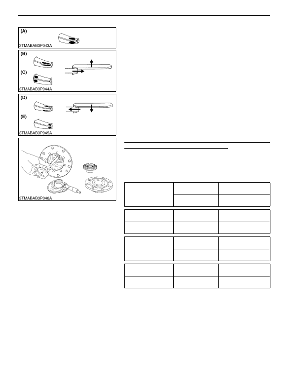
More than 35 % contact area on the gear tooth surface.
The center of tooth contact at 1/3 of the entire width from the
small end.
Replace the adjusting shim (2) with thicker one to move the
spiral bevel pinion shaft backward.
For move the spiral bevel gear rightward, reduce right side shim
(5) and add shim (6) of the same thickness as the right side to left
side.
Replace the shim (2) with a thinner one to move the spiral bevel
pinion shaft forward.
For move the spiral bevel gear leftward, reduce left side shim (6)
and add shim (5) of the same thickness as the left side to right side.
Repeat above until the proper tooth contact and backlash are
achieved.
9Y1210824TRS0141US0
Clearance between Differential Case Bore (Differential Case
Cover Bore) and Differential Side Gear Boss
1. Measure the bore I.D. of the differential case and differential
case cover.
2. Measure the differential side gear boss O.D. and calculate the
clearance.
3. If the clearance exceeds the allowable limit, replace them.
9Y1210824TRS0142US0
(A) Proper Contact
(B) Shallow Contact
(C) Heel Contact
(D) Deep Contact
(E) Toe Contact
Clearance between
differential case bore and
differential side gear
boss
Factory specification
0.050 to 0.151 mm
0.0020 to 0.00594 in.
Allowable limit
0.35 mm
0.014 in.
Differential case bore
I.D.
Factory specification
40.500 to 40.550 mm
1.5945 to 1.5964 in.
Differential side gear
boss O.D.
Factory specification
40.388 to 40.450 mm
1.5901 to 1.5925 in.
Clearance between
differential case cover
bore and differential side
gear boss
Factory specification
0.050 to 0.151 mm
0.0020 to 0.00594 in.
Allowable limit
0.35 mm
0.014 in.
Differential case cover
bore I.D.
Factory specification
40.500 to 40.550 mm
1.5945 to 1.5964 in.
Differential side gear
boss O.D.
Factory specification
40.388 to 40.450 mm
1.5901 to 1.5925 in.
KiSC issued 03, 2016 A
Detailed Information for Kubota L3560 Owners Manual
Lists of information found in Kubota L3560 Owners Manual - Page 447
- 1. Measure the bore I.
- 2. Measure the differential side gear boss O.
- 3. If the clearance exceeds the allowable limit, replace them.
- 1.5945 to 1.
- 1.5901 to 1.
- 1.5945 to 1.
- 1.5901 to 1.