(2) Disassembling Hydraulic Assembly; Lowering Speed Adjusting Valve; Check Valves- Page 572
Kubota L3560 Owners Manual
Table of Contents
HYDRAULIC SYSTEM
L3560, L4060, L4760, L5060, L5460, L6060, WSM
8-S19
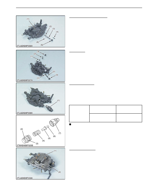
(2) Disassembling Hydraulic Assembly
Lowering Speed Adjusting Valve
1. Draw out the spring pin (4).
2. Remove the holder (5).
3. Draw out the lowering speed adjusting shaft (3), dowel pin (6)
and rotor (2).
(When reassembling)
• Be careful not to damage the O-rings.
9Y1210824HYS0020US0
Check Valves
1. Remove the plug (3).
2. Draw out the spring (2) and poppet (1).
(When reassembling)
• Be careful not to damage the O-ring.
9Y1210824HYS0021US0
Cylinder Safety Valve
1. Remove the cylinder safety valve assembly (1).
2. Secure the cylinder safety valve assembly in a vise.
3. Loosen the lock nut (3), and remove the adjust screw (2).
4. Draw out the spring (4), seat (5), and ball (6).
(When reassembling)
• Be careful not to damage the O-rings.
IMPORTANT
• After disassembling and assembling the cylinder safety
valve assembly, be sure to check the operating pressure.
9Y1210824HYS0022US0
Position Control Valve
1. Remove the position control valve (1) from rear hydraulic block
(2).
(When reassembling)
• Be careful not to damage the O-rings.
9Y1210824HYS0023US0
(1) Rear Hydraulic Block
(2) Rotor
(3) Lowering Speed Adjusting Shaft
(4) Spring Pin
(5) Holder
(6) Dowel Pin
(1) Poppet
(2) Spring
(3) Plug
Tightening torque
Cylinder safety valve
assembly
40 to 49 N·m
4.0 to 5.0 kgf·m
29 to 36 lbf·ft
Cylinder safety valve lock
nut
59 to 78 N·m
6.0 to 8.0 kgf·m
44 to 57 lbf·ft
(1) Cylinder Safety Valve Assembly
(2) Adjusting Screw
(3) Lock Nut
(4) Spring
(5) Seat
(6) Ball
(7) Housing
(1) Position Control Valve
(2) Rear Hydraulic Block
KiSC issued 03, 2016 A
Detailed Information for Kubota L3560 Owners Manual
Lists of information found in Kubota L3560 Owners Manual - Page 572
- 1. Draw out the spring pin (4).
- 2. Remove the holder (5).
- 3. Draw out the lowering speed adjusting shaft (3), dowel pin (6) and rotor (2).
- 1. Remove the plug (3).
- 2. Draw out the spring (2) and poppet (1).
- 1. Remove the cylinder safety valve assembly (1).
- 2. Secure the cylinder safety valve assembly in a vise.
- 3. Loosen the lock nut (3), and remove the adjust screw (2).
- 4. Draw out the spring (4), seat (5), and ball (6).
- 1. Remove the position control valve (1) from rear hydraulic block (2).
- 4.0 to 5.
- 6.0 to 8.
- Be careful not to damage the O-rings.
- Be careful not to damage the O-ring.
- Be careful not to damage the O-rings.
- After disassembling and assembling the cylinder safety valve assembly, be sure to check the operating pressure.
- Be careful not to damage the O-rings.