1) Connector Voltage; 2) Switch Continuity; 2) Light Switch and Turn Signal Light Switch Continuity- Page 708
Kubota L3560 Owners Manual
Table of Contents
ELECTRICAL SYSTEM
L3560, L4060, L4760, L5060, L5460, L6060, WSM
9-S70
2) Light Switch and Turn Signal Light Switch Continuity
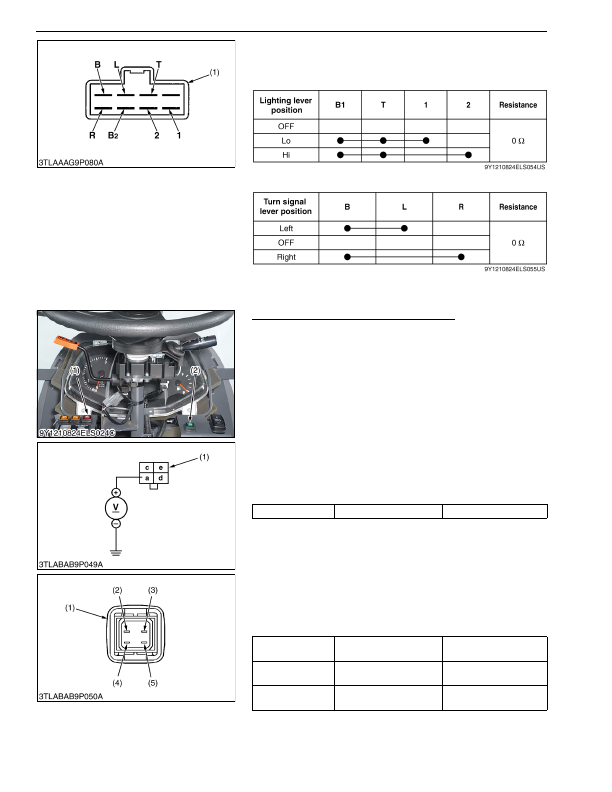
1. Measure the resistance across seven terminal referring to the
table below.
[Light Switch]
[Turn Signal Switch]
9Y1210824ELS0086US0
Hazard Switch and Side Work Light Switch
1. Remove the meter panel cover and disconnect the
4P
connector from switch (1) (2) after disconnect the battery
negative code.
2. Remove the switch (1) (2).
3. Perform the following checking.
9Y1210824ELS0087US0
1) Connector Voltage
1. Connect the battery negative code, then measure the voltage
across the terminal
a
and chassis.
2. If the voltage differ from the battery voltage, the wiring harness
is faulty.
9Y1210824ELS0088US0
2) Switch Continuity
1. Measure the resistance with ohmmeter across the terminal
a
and terminal
c
, and across the terminal
d
and terminal
e
.
2. If the measurement is not following below, the hazard switch or
the bulb are faulty.
9Y1210824ELS0089US0
(1) Multi Combination Lever Switch
(1) Hazard Switch
(2) Side Work Light Switch
Voltage
Terminal
a
– Chassis
Approx. battery voltage
(1) Connector of Wire Harness Side
Resistance
(Switch at
OFF
)
Terminal
a
– Terminal
c
Infinity
Resistance
(Switch at
ON
)
Terminal
a
– Terminal
c
0 Ω
Resistance
(Bulb)
Terminal
d
– Terminal
e
Approx. 13 Ω
(1) Hazard Switch Connector
(2) Terminal
a
(3) Terminal
d
(4) Terminal
c
(5) Terminal
e
KiSC issued 03, 2016 A
Detailed Information for Kubota L3560 Owners Manual
Lists of information found in Kubota L3560 Owners Manual - Page 708
- 1. Measure the resistance across seven terminal referring to the table below.
- 1. Remove the meter panel cover and disconnect the 4P connector from switch (1) (2) after disconnect the battery negative code.
- 2. Remove the switch (1) (2).
- 3. Perform the following checking.
- 1. Connect the battery negative code, then measure the voltage across the terminal a and chassis.
- 2. If the voltage differ from the battery voltage, the wiring harness is faulty.
- 1. Measure the resistance with ohmmeter across the terminal a and terminal c , and across the terminal d and terminal e .
- 2. If the measurement is not following below, the hazard switch or the bulb are faulty.