(6) Engine ECU Power Relay, Glow Relay and Defogger Relay; Checking Connector Voltage; Functional Check- Page 705
Kubota L3560 Owners Manual
Table of Contents
ELECTRICAL SYSTEM
L3560, L4060, L4760, L5060, L5460, L6060, WSM
9-S67
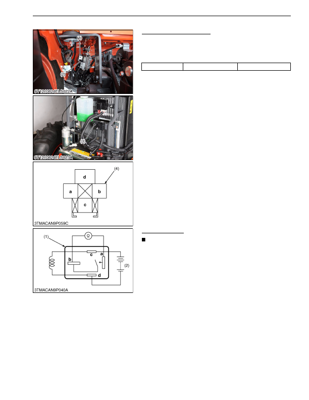
(6) Engine ECU Power Relay, Glow Relay and Defogger Relay
Checking Connector Voltage
1. Measure the voltage with a voltmeter across the battery terminal
and chassis as table below.
2. If the voltage differs from the battery voltage, the wiring harness
or fuse is faulty.
9Y1210824ELS0077US0
Functional Check
NOTE
• The relays described here are used same ones so that
these are interchangeable.
1. Apply battery voltage across the terminals
c
and
d
, and check
for continuity across the terminals
a
and
b
.
2. If continuity is not established across the terminals
a
and
b
,
replace it.
9Y1210824ELS0078US0
Voltage
Terminal
d
– Chassis
Approx. battery voltage
(1) Engine ECU Relay
(2) Glow Relay
(3) Defogger Relay (CABIN Type Only)
(4) Connector (Wire Harness side)
(1) Connector (Relay)
(2) Battery
KiSC issued 03, 2016 A
Detailed Information for Kubota L3560 Owners Manual
Lists of information found in Kubota L3560 Owners Manual - Page 705
- 1. Measure the voltage with a voltmeter across the battery terminal and chassis as table below.
- 2. If the voltage differs from the battery voltage, the wiring harness or fuse is faulty.
- 1. Apply battery voltage across the terminals c and d , and check for continuity across the terminals a and b .
- 2. If continuity is not established across the terminals a and b , replace it.
- The relays described here are used same ones so that these are interchangeable.