(2) SCV (Suction Control Valve); Connector Voltage- Page 714
Kubota L3560 Owners Manual
Table of Contents
ELECTRICAL SYSTEM
L3560, L4060, L4760, L5060, L5460, L6060, WSM
9-S76
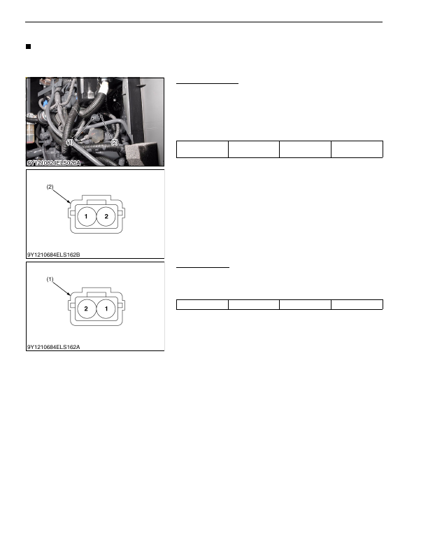
(2) SCV (Suction Control Valve)
NOTE
• Firstly check the connector voltage, secondly check the other wires continuity, then finally check the SCV
resistance.
9Y1210824ELS0101US0
Connector Voltage
1. Disconnect the connector, and turn the main key switch
"ON"
position.
2. Measure the voltage with a voltmeter across the terminals
shown in the table below.
3. If the reference value is not indicated as shown in the table
below, check the relating electric circuit.
9Y1210824ELS0102US0
SCV Resistance
1. Measure the resistance with an ohmmeter across the terminals
shown in the table below.
2. If the reference value is not indicated, the SCV is faulty.
9Y1210824ELS0103US0
Voltage
Main switch at
"ON"
Terminal
2
–
chassis
Approx. battery
voltage
(1) SCV (Suction Control Valve)
(2) Connector (Harness Side)
Resistance
at 20 °C (68 °F)
Terminal
1
–
2
2.60 to 3.15 Ω
(1) Connector (SCV Side)
KiSC issued 03, 2016 A
Detailed Information for Kubota L3560 Owners Manual
Lists of information found in Kubota L3560 Owners Manual - Page 714
- 1. Disconnect the connector, and turn the main key switch "ON" position.
- 2. Measure the voltage with a voltmeter across the terminals shown in the table below.
- 3. If the reference value is not indicated as shown in the table below, check the relating electric circuit.
- 1. Measure the resistance with an ohmmeter across the terminals shown in the table below.
- 2. If the reference value is not indicated, the SCV is faulty.
- 2.60 to 3.
- Firstly check the connector voltage, secondly check the other wires continuity, then finally check the SCV resistance.