(5) Boost Sensor (If Equipped); Connector Voltage; circuit is normal.- Page 717
Kubota L3560 Owners Manual
Table of Contents
L3560,L4060,L4760,L5060,L5460,L6060
ELECTRICAL SYSTEM
L3560, L4060, L4760, L5060, L5460, L6060, WSM
9-S79
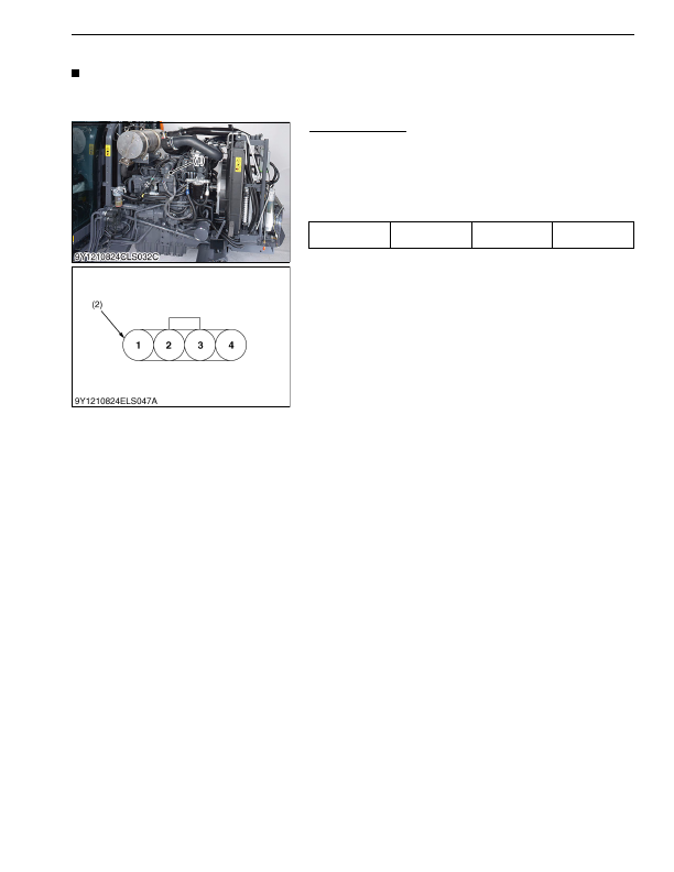
(5) Boost Sensor (If Equipped)
NOTE
• Since it is not possible to do unit checking for this sensor, judge the sensor is faulty if the relating electric
circuit is normal.
9Y1210824ELS0109US0
Connector Voltage
1. Disconnect the connector, and turn the main key switch
"ON"
position.
2. Measure the voltage with a voltmeter across the terminals
shown in the table below.
3. If the reference value is not indicated as shown in the table
below, check the relating electric circuit.
9Y1210824ELS0110US0
Voltage
Main switch at
"ON"
Terminal
3
–
chassis
Approx. 5 V
(1) Boost Sensor
(2) Connector (Harness Side)
KiSC issued 03, 2016 A
Detailed Information for Kubota L3560 Owners Manual
Lists of information found in Kubota L3560 Owners Manual - Page 717
- 1. Disconnect the connector, and turn the main key switch "ON" position.
- 2. Measure the voltage with a voltmeter across the terminals shown in the table below.
- 3. If the reference value is not indicated as shown in the table below, check the relating electric circuit.
- Since it is not possible to do unit checking for this sensor, judge the sensor is faulty if the relating electric circuit is normal.