Panel Frame; Hydraulic Pipes- Page 180
Kubota L3560 Owners Manual
Table of Contents
ENGINE
L3560, L4060, L4760, L5060, L5460, L6060, WSM
1-S33
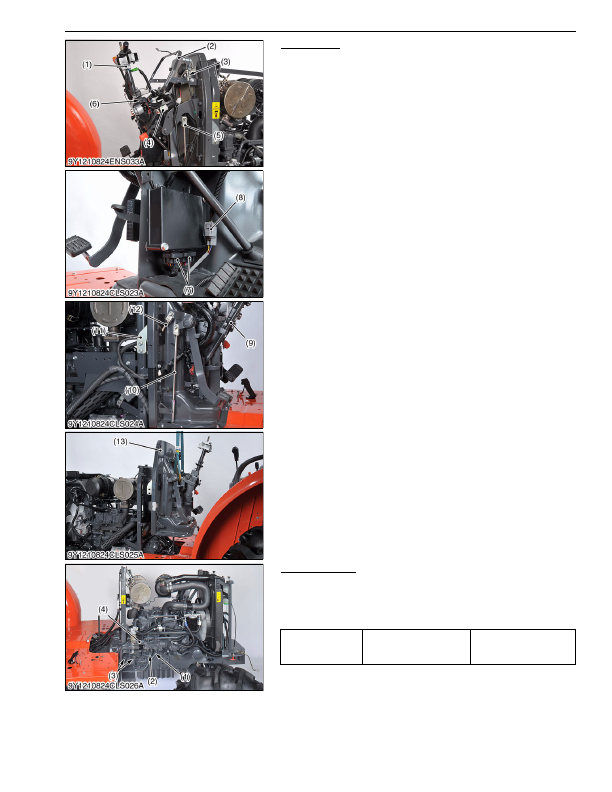
Panel Frame
1. Disconnect the multi function combination switch connector (1),
side working light connector (6) and main switch connector (4).
2. Disconnect the foot throttle wire (3) and shuttle switch connector
(8) (Manual Transmission and GST only)
3. Remove the meter panel support (2) and brake pedal rod R.H.
(5).
4. Remove the main ECU connectors (7).
5. Remove the shuttle link (9) and clutch pedal rod (12). (Manual
transmission and GST only)
6. Remove the shuttle link (9), brake pedal rod L.H. (10), clutch
pedal rod (12) and both sides of support plate (11).
7. Remove the panel frame (13) using the hoist.
9Y1210824ENS0129US0
Hydraulic Pipes
1. Disconnect the delivery pipe (1), PTO delivery pipe (2) and
suction hose (4) from the hydraulic pump.
2. Remove the front loader pipe bracket mounting bolts (3).
(When reassembling)
9Y1210824CLS0011US0
(1) Multi Function Combination Switch
(2) Meter Panel Support
(3) Foot Throttle Wire
(4) Main Switch Connector
(5) Brake Pedal Rod R.H.
(6) Front Working Light Connector
(7) Main ECU Connector
(8) Shuttle Switch Connector
(9) Shuttle Link
(10) Brake Pedal Rod L.H.
(11) Rear Support Plate
(12) Clutch Pedal Rod
(13) Panel Frame
Tightening torque
Joint bolt for PTO delivery
pipe
35 to 39 N·m
3.5 to 4.0 kgf·m
26 to 28 lbf·ft
(1) Delivery Pipe
(2) PTO Delivery Pipe
(3) Bolt
(4) Suction Hose
KiSC issued 03, 2016 A
Detailed Information for Kubota L3560 Owners Manual
Lists of information found in Kubota L3560 Owners Manual - Page 180
- 1. Disconnect the multi function combination switch connector (1), side working light connector (6) and main switch connector (4).
- 2. Disconnect the foot throttle wire (3) and shuttle switch connector (8) (Manual Transmission and GST only) 3.
- 4. Remove the main ECU connectors (7).
- 5. Remove the shuttle link (9) and clutch pedal rod (12).
- 6. Remove the shuttle link (9), brake pedal rod L.
- 7. Remove the panel frame (13) using the hoist.
- 1. Disconnect the delivery pipe (1), PTO delivery pipe (2) and suction hose (4) from the hydraulic pump.
- 2. Remove the front loader pipe bracket mounting bolts (3).
- 3.5 to 4.