Fuel Hoses and Pillar; Turbocharger (If Equipped)- Page 182
Kubota L3560 Owners Manual
Table of Contents
ENGINE
L3560, L4060, L4760, L5060, L5460, L6060, WSM
1-S35
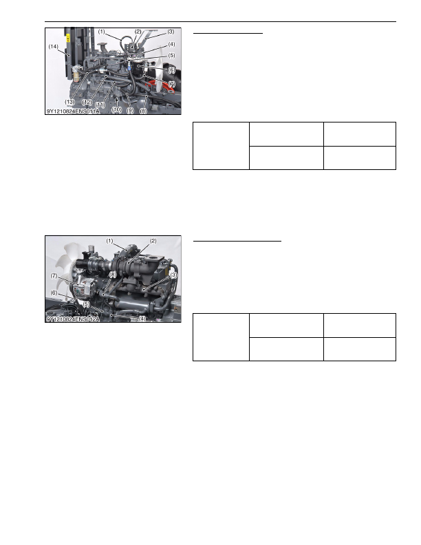
Fuel Hoses and Pillar
1. Disconnect the overflow hose (1) and fuel hoses (4), then
remove the bracket (3) together with fuel sub tank (2).
2. Disconnect the overflow hose (5), fuel hose (7), (9), (13), then
remove the fuel filter (6).
3. Disconnect the power steering return hose (12) and fuel hose
(8).
4. Remove the power steering delivery pipe (11).
5. Remove the dipstick stay (10).
6. Remove the pillar (14).
(When reassembling)
9Y1210824ENS0020US0
Turbocharger (If Equipped)
1. Disconnect the air intake hose (1).
2. Remove the fan belt (6) and alternator (7)
3. Remove the EGR cooler hose (8) and cooler pipe.
4. Disconnect the oil pipe (5) and return hose (4).
5. Remove the exhaust manifold (3) together with turbocharger
(2).
(When reassembling)
• Be sure to adjust the fan belt tension. (See page 1-S14.)
9Y1210824ENS0021US0
Tightening torque
Joint bolt for power steering
delivery pipe
40 to 49 N·m
4.0 to 5.0 kgf·m
29 to 36 lbf·ft
Retaining nut of power
steering delivery pipe
49 to 58 N·m
5.0 to 6.0 kgf·m
37 to 43 lbf·ft
(1) Overflow Hose
(2) Fuel Sub Tank
(3) Bracket
(4) Fuel Hose
(5) Overflow Hose
(6) Fuel Filter
(7) Fuel Hose
(8) Fuel Hose
(9) Fuel Hose
(10) Dipstick Stay
(11) Power Steering Delivery Pipe
(12) Power Steering Return Hose
(13) Fuel Hose
(14) Pillar
Tightening torque
Alternator mounting screw
(M10)
40 to 44 N·m
4.0 to 4.5 kgf·m
29 to 32 lbf·ft
Tension adjusting Screw
(M8)
18 to 20 N·m
1.8 to 2.1 kgf·m
13 to 15 lbf·ft
(1) Intake Hose
(2) Turbocharger
(3) Exhaust Manifold
(4) Return Hose
(5) Oil Pipe
(6) Fan Belt
(7) Alternator
(8) EGR Cooler Hose
KiSC issued 03, 2016 A
Detailed Information for Kubota L3560 Owners Manual
Lists of information found in Kubota L3560 Owners Manual - Page 182
- 1. Disconnect the overflow hose (1) and fuel hoses (4), then remove the bracket (3) together with fuel sub tank (2).
- 2. Disconnect the overflow hose (5), fuel hose (7), (9), (13), then remove the fuel filter (6).
- 3. Disconnect the power steering return hose (12) and fuel hose (8).
- 4. Remove the power steering delivery pipe (11).
- 5. Remove the dipstick stay (10).
- 6. Remove the pillar (14).
- 1. Disconnect the air intake hose (1).
- 2. Remove the fan belt (6) and alternator (7) 3.
- 4. Disconnect the oil pipe (5) and return hose (4).
- 5. Remove the exhaust manifold (3) together with turbocharger (2).
- 14.) 9Y1210824ENS0021US0 Tightening torque Joint bolt for power steering delivery pipe 40 to 49 N·m 4.
- 5.0 kgf·m 29 to 36 lbf·ft Retaining nut of power steering delivery pipe 49 to 58 N·m 5.
- 6.0 kgf·m 37 to 43 lbf·ft (1) Overflow Hose (2) Fuel Sub Tank (3) Bracket (4) Fuel Hose (5) Overflow Hose (6) Fuel Filter (7) Fuel Hose (8) Fuel Hose (9) Fuel Hose (10) Dipstick Stay (11) Power Steering Delivery Pipe (12) Power Steering Return Hose (13) Fuel Hose (14) Pillar Tightening torque Alternator mounting screw (M10) 40 to 44 N·m 4.
- 4.5 kgf·m 29 to 32 lbf·ft Tension adjusting Screw (M8) 18 to 20 N·m 1.
- Be sure to adjust the fan belt tension.