Spiral Bevel Gear; A: Fit Groove; Differential Case Cover and Differential Side Gear- Page 396
Kubota L3560 Owners Manual
Table of Contents
TRANSMISSION
L3560, L4060, L4760, L5060, L5460, L6060, WSM
3-S77
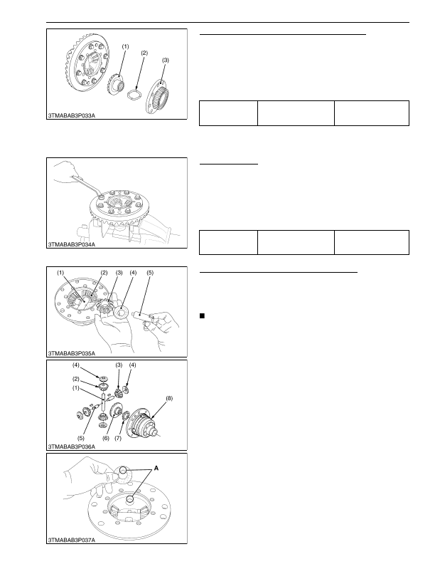
Differential Case Cover and Differential Side Gear
1. Remove the differential case cover (3).
2. Remove the differential side gear (1) and differential side gear
washer (2).
(When reassembling)
• Apply molybdenum disulfide (Three Bond 1901 or equivalent) to
the inner circumferential surface of the differential side gear
boss.
9Y1210824TRS0046US0
Spiral Bevel Gear
1. Remove the spiral bevel gear.
(When reassembling)
• Check the spiral bevel gear for wear or damage. If it is no longer
serviceable, replace it. Then, also replace the spiral bevel pinion
shaft.
• Apply liquid lock (Three Bond 1372 or equivalent) to the spiral
bevel gear UBS screws.
9Y1210824TRS0047US0
Differential Pinion Shaft and Differential Pinion
1. Draw out the differential pinion shaft 2 (5), and remove the
differential pinion (3) and differential pinion washer (4).
2. Draw out the differential pinion shaft (1), and remove the
differential pinion (2) and differential pinion washer.
NOTE
• Arrange the parts to know their original position.
(When reassembling)
• Check the differential pinions (2) and (3), and pinion shaft (1)
and (5) for excessive wear. If these parts are damaged or
excessively worn, replace their parts they are in mesh with, or
they sliding on.
• Apply molybdenum disulfide (Three Bond 1901 or equivalent) to
the inner circumferential surface of the differential pinions.
• Install the parts to their original position.
• Install the differential pinion washer (4), noting its groove
position.
9Y1210824TRS0048US0
Tightening torque
Differential case cover
mounting screw
48 to 55 N·m
4.9 to 5.7 kgf·m
36 to 41 lbf·ft
(1) Differential Side Gear
(2) Differential Side Gear Washer
(3) Differential Case Cover
Tightening torque
Spiral bevel gear UBS
screw
69 to 88 N·m
7.0 to 9.0 kgf·m
51 to 65 lbf·ft
(1) Differential Pinion Shaft
(2) Differential Pinion
(3) Differential Pinion
(4) Differential Pinion Washer
(5) Differential Pinion Shaft 2
(6) Differential Side Gear
(7) Differential Side Gear Washer
(8) Differential Case
A: Fit Groove
KiSC issued 03, 2016 A
Detailed Information for Kubota L3560 Owners Manual
Lists of information found in Kubota L3560 Owners Manual - Page 396
- 1. Remove the differential case cover (3).
- 2. Remove the differential side gear (1) and differential side gear washer (2).
- 1. Remove the spiral bevel gear.
- 1. Draw out the differential pinion shaft 2 (5), and remove the differential pinion (3) and differential pinion washer (4).
- 2. Draw out the differential pinion shaft (1), and remove the differential pinion (2) and differential pinion washer.
- 4.9 to 5.
- 7.0 to 9.
- Apply molybdenum disulfide (Three Bond 1901 or equivalent) to the inner circumferential surface of the differential side gear boss.
- Check the spiral bevel gear for wear or damage.
- Apply liquid lock (Three Bond 1372 or equivalent) to the spiral bevel gear UBS screws.
- Arrange the parts to know their original position.
- Check the differential pinions (2) and (3), and pinion shaft (1) and (5) for excessive wear.
- Apply molybdenum disulfide (Three Bond 1901 or equivalent) to the inner circumferential surface of the differential pinions.
- Install the parts to their original position.
- Install the differential pinion washer (4), noting its groove position.