Pinion Bearing Cover; Separating Mid Case and Transmission Case- Page 392
Kubota L3560 Owners Manual
Table of Contents
TRANSMISSION
L3560, L4060, L4760, L5060, L5460, L6060, WSM
3-S73
Separating Mid Case and Transmission Case
1. Separate the mid case and transmission case after removing
their mounting screws and nut.
(When reassembling)
• Make sure to insert the PTO shaft to PTO clutch firmly, turning
the PTO shaft.
• Make sure to insert the front wheel drive shaft to coupling firmly.
• Apply liquid gasket (Three Bond 1208C or equivalent) to joint
face of the mid case and transmission case.
9Y1210824TRS0037US0
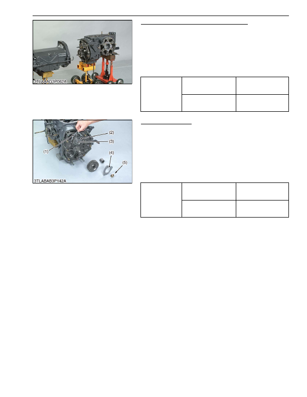
Pinion Bearing Cover
1. Remove the stake of lock nut (5).
2. Lock the turning of spiral bevel pinion and remove the lock nut
(5).
3. Remove the pinion bearing case mounting screws.
4. Remove the pinion bearing cover (4) and shims (1).
(When reassembling)
• Make sure of the number of shims in the pinion bearing case.
• Replace the lock nut (5) with a new one, and stake the lock nut
firmly after installing the parts on the shaft.
9Y1210824TRS0038US0
Tightening torque
Mid case and transmission
case mounting screw
78 to 90 N·m
7.9 to 9.2 kgf·m
58 to 66 lbf·ft
Mid case and transmission
case mounting nut
103 to 117 N·m
10.5 to 12.0 kgf·m
76.0 to 86.7 lbf·ft
Tightening torque
Lock nut
150 to 190 N·m
15 to 20 kgf·m
110 to 140 lbf·ft
Pinion bearing case
mounting screw
40 to 44 N·m
4.0 to 4.5 kgf·m
29 to 32 lbf·ft
(1) Shim
(2) Pinion Bearing Case
(3) Spiral Bevel Pinion Shaft
(4) Pinion Bearing Cover
(5) Lock Nut
KiSC issued 03, 2016 A
Detailed Information for Kubota L3560 Owners Manual
Lists of information found in Kubota L3560 Owners Manual - Page 392
- 1. Separate the mid case and transmission case after removing their mounting screws and nut.
- 1. Remove the stake of lock nut (5).
- 2. Lock the turning of spiral bevel pinion and remove the lock nut (5).
- 3. Remove the pinion bearing case mounting screws.
- 4. Remove the pinion bearing cover (4) and shims (1).
- 7.9 to 9.
- 12.0 kgf·m 76.
- 86.7 lbf·ft Tightening torque Lock nut 150 to 190 N·m 15 to 20 kgf·m 110 to 140 lbf·ft Pinion bearing case mounting screw 40 to 44 N·m 4.
- Make sure to insert the PTO shaft to PTO clutch firmly, turning the PTO shaft.
- Make sure to insert the front wheel drive shaft to coupling firmly.
- Apply liquid gasket (Three Bond 1208C or equivalent) to joint face of the mid case and transmission case.
- Make sure of the number of shims in the pinion bearing case.
- Replace the lock nut (5) with a new one, and stake the lock nut firmly after installing the parts on the shaft.