Dump 1; Pump Port; Tank Port- Page 549
Kubota L3560 Owners Manual
Table of Contents
HYDRAULIC SYSTEM
L3560, L4060, L4760, L5060, L5460, L6060, WSM
8-M20
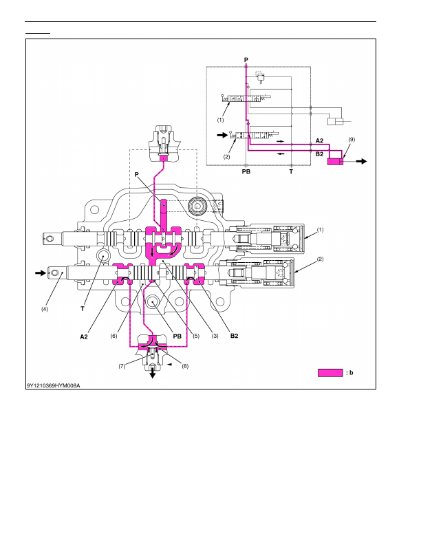
Dump 1
1. When the hydraulic control lever is set to the
"DUMP 1"
position, the spool (4), which forms oil passages among
passage 2 (8),
A2
port and
B2
port moves to the right.
2. The pressure-fed oil from the
P
port flows through the boom control valve, opens the load check valve, and flows
to the bracket cylinder to extend the cylinder through the notched section of the spool and
A2
port.
3. Return oil from the bucket cylinder (9) flows from the
B2
port to the passage 2 (8), and flows to the
A2
port
together with the pressure-fed oil from the
P
port.
As a result, the dump speed is increased.
(Reference)
• The oil pressure of the
A2
port and
B2
port is identical, but the bucket cylinder extend by the difference of received
pressure area (cylinder rod part).
9Y1210824HYM0023US0
(1) Boom Control Section
(2) Bucket Control Section
(3)
PB
Passage 1
(4) Spool
(5) Neutral Passage 2
(6)
PB
Passage 2
(7) Load Check Valve
(8) Passage 2
(9) Bucket Cylinder
P:
Pump Port
T:
Tank Port
PB: Power Beyond Port
A2: A2 Port
(To Bucket Cylinder)
B2: B2 Port
(From Bucket Cylinder)
b:
High Pressure
KiSC issued 03, 2016 A
Detailed Information for Kubota L3560 Owners Manual
Lists of information found in Kubota L3560 Owners Manual - Page 549
- 1. When the hydraulic control lever is set to the "DUMP 1" position, the spool (4), which forms oil passages among passage 2 (8), A2 port and B2 port moves to the right.
- 2. The pressure-fed oil from the P port flows through the boom control valve, opens the load check valve, and flows to the bracket cylinder to extend the cylinder through the notched section of the spool and A2 port.
- 3. Return oil from the bucket cylinder (9) flows from the B2 port to the passage 2 (8), and flows to the A2 port together with the pressure-fed oil from the P port.
- The oil pressure of the A2 port and B2 port is identical, but the bucket cylinder extend by the difference of received pressure area (cylinder rod part).