Propeller Shaft; Separating Engine from Clutch Housing and Front Axle Frame- Page 198
Kubota L3560 Owners Manual
Table of Contents
ENGINE
L3560, L4060, L4760, L5060, L5460, L6060, WSM
1-S51
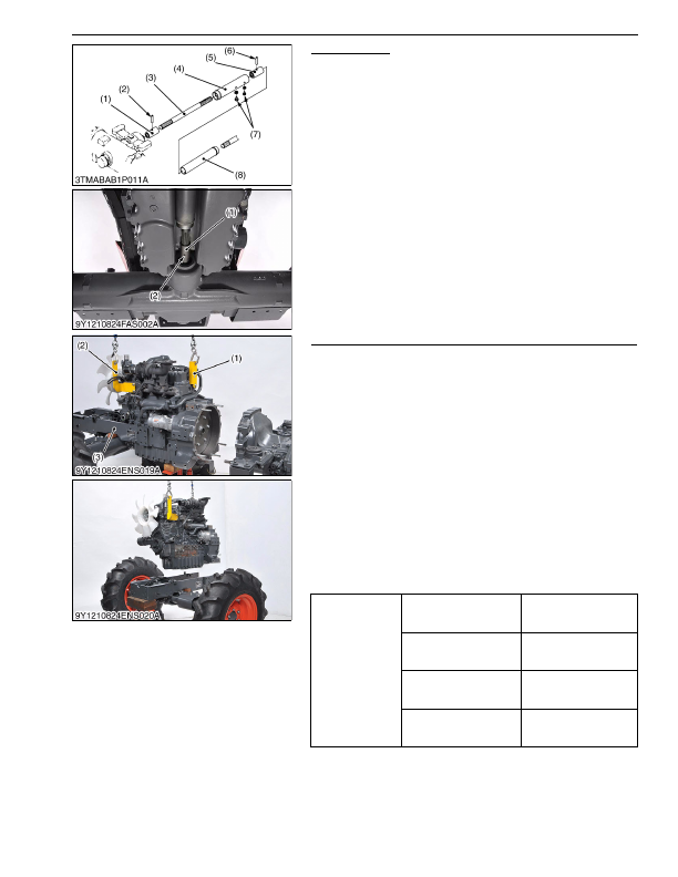
Propeller Shaft
1. Slide the propeller shaft cover (4) and (8) after removing the
screws (7).
2. Tap out the spring pins (2), (6) and slide the couplings (1), (5)
and then remove the propeller shaft with covers (4), (8).
(When reassembling)
• Apply grease to the splines of propeller shaft (3).
9Y1210824FAS0009US0
Separating Engine from Clutch Housing and Front Axle Frame
1. Place the disassembling stands under the engine and clutch
housing.
2. Remove the engine and clutch housing mounting screws and
nuts.
3. Separate the engine and clutch housing.
4. [L3560]
Remove one of the two engine hooks attached on the left side
of the engine and install it on the right rear side of the engine.
[except L3560]
Install the engine hooks (1), (2). (See page G-61, G-62.)
5. Hold the engine by the hoist chain hooked on the engine hooks
(1) and (2).
6. Remove the engine mounting screws.
7. Lift up the engine to separate from the front axle frame (3).
(When reassembling)
• Apply grease to the spline of clutch shaft.
• Apply liquid gasket (Three Bond 1211 or equivalent) to joint face
of the flywheel housing and clutch housing.
9Y1210824ENS0027US0
(1) Coupling
(2) Spring Pin
(3) Propeller Shaft
(4) Propeller Shaft Cover
(5) Coupling
(6) Spring Pin
(7) Screws
(8) Propeller Shaft Cover
Tightening torque
Engine and clutch housing
mounting screw
78 to 90 N·m
7.9 to 9.2 kgf·m
58 to 66 lbf·ft
Engine and clutch housing
mounting nut
103 to 117 N·m
10.5 to 12.0 kgf·m
76.0 to 86.7 lbf·ft
Front axle frame mounting
screw (7T)
78 to 90 N·m
7.9 to 9.2 kgf·m
58 to 66 lbf·ft
Front axle frame mounting
screw (9T)
103 to 117 N·m
10.5 to 12.0 kgf·m
76.0 to 86.7 lbf·ft
(1) Engine Hook
(2) Engine Hook
(3) Front Axle Frame
KiSC issued 03, 2016 A
Detailed Information for Kubota L3560 Owners Manual
Lists of information found in Kubota L3560 Owners Manual - Page 198
- 1. Slide the propeller shaft cover (4) and (8) after removing the screws (7).
- 2. Tap out the spring pins (2), (6) and slide the couplings (1), (5) and then remove the propeller shaft with covers (4), (8).
- 1. Place the disassembling stands under the engine and clutch housing.
- 2. Remove the engine and clutch housing mounting screws and nuts.
- 3. Separate the engine and clutch housing.
- 4. [L3560] Remove one of the two engine hooks attached on the left side of the engine and install it on the right rear side of the engine.
- 62.) 5.
- 6. Remove the engine mounting screws.
- 7. Lift up the engine to separate from the front axle frame (3).
- 7.9 to 9.
- 12.0 kgf·m 76.
- 86.7 lbf·ft Front axle frame mounting screw (7T) 78 to 90 N·m 7.
- 9.2 kgf·m 58 to 66 lbf·ft Front axle frame mounting screw (9T) 103 to 117 N·m 10.
- 12.0 kgf·m 76.
- Apply grease to the splines of propeller shaft (3).
- Apply grease to the spline of clutch shaft.
- Apply liquid gasket (Three Bond 1211 or equivalent) to joint face of the flywheel housing and clutch housing.