crankshaft. Measure it when you assemble again.; hole of the main bearing case 2 (2) with the screw hole of; the cylinder block.- Page 221
Kubota L3560 Owners Manual
Table of Contents
ENGINE
L3560, L4060, L4760, L5060, L5460, L6060, WSM
1-S74
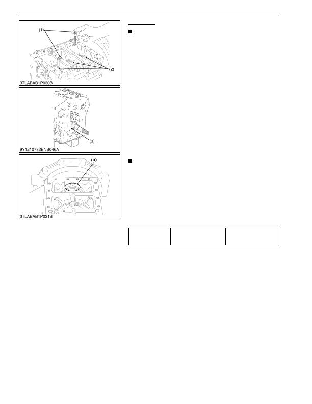
Crankshaft
NOTE
• Before you disassemble, measure the side clearance of
crankshaft. Measure it when you assemble again.
[D1803-CR-E4]
1. Remove the screw 2 (1) of the main bearing case.
2. Turn the crankshaft to set the crankpin of the third cylinder to the
bottom dead center.
3. Pull out the crankshaft until the crankpin of the second cylinder
comes to the center of the third cylinder.
4. Turn the crankshaft by 2.09 rad (120 °) counterclockwise to set
the crankpin of the second cylinder to the bottom dead center.
5. Pull out the crankshaft until the crankpin of the first cylinder
comes to the center of the third cylinder.
6. Do the above steps again to pull out the crankshaft completely.
[V2403-CR-E4, V2403-CR-TE4]
1. Remove the screw 2 (1) of the main bearing case.
2. Turn the crankshaft to set the crankpin of the fourth cylinder to
the horizontal directions (right or left).
3. Hold the crankpins to the horizontal directions (right or left) and
pull out the crankshaft completely.
(When reassembling)
IMPORTANT
• When you install the crankshaft assembly, align the screw
hole of the main bearing case 2 (2) with the screw hole of
the cylinder block.
• Apply oil to the screw 2 (1) of the main bearing case and
tighten the screw by hand.
If you cannot turn the screw 2 smoothly, align the screw
holes between the cylinder block and the main bearing
case correctly.
Then tighten the screw 2 to the specified tightening torque
with a torque wrench.
9Y1210824ENS0066US0
Tightening torque
Screw 2 of main bearing
case
69 to 73 N·m
7.0 to 7.5 kgf·m
51 to 54 lbf·ft
(1) Screw 2 of Main Bearing Case
(2) Main Bearing Case 2
(3) Crankshaft Bearing 1
(a) Cut place to remove and install
the crankshaft
KiSC issued 03, 2016 A
Detailed Information for Kubota L3560 Owners Manual
Lists of information found in Kubota L3560 Owners Manual - Page 221
- 1. Remove the screw 2 (1) of the main bearing case.
- 2. Turn the crankshaft to set the crankpin of the third cylinder to the bottom dead center.
- 3. Pull out the crankshaft until the crankpin of the second cylinder comes to the center of the third cylinder.
- 4. Turn the crankshaft by 2.
- 5. Pull out the crankshaft until the crankpin of the first cylinder comes to the center of the third cylinder.
- 6. Do the above steps again to pull out the crankshaft completely.
- 1. Remove the screw 2 (1) of the main bearing case.
- 2. Turn the crankshaft to set the crankpin of the fourth cylinder to the horizontal directions (right or left).
- 3. Hold the crankpins to the horizontal directions (right or left) and pull out the crankshaft completely.
- 7.0 to 7.
- Before you disassemble, measure the side clearance of crankshaft.
- When you install the crankshaft assembly, align the screw hole of the main bearing case 2 (2) with the screw hole of the cylinder block.
- Apply oil to the screw 2 (1) of the main bearing case and tighten the screw by hand.